Digital Twins for Stator & Rotor Parts: Tying CAD, FEA, & QC Data for Peak Performance
Every engineer knows that the difference between a winning motor design and a series of headaches often comes down to how well you bridge the gap between the digital and physical worlds. Maybe you’ve stared at the perfect CAD drawing, only to watch the manufactured motor come off the line with unexpected deviations or nagging quality issues. Or perhaps you’ve poured hours into FEA simulations, but the real-world assembly doesn’t quite match the predicted performance. If integrating CAD, FEA, and QC data for stator and rotor laminations keeps you up at night, you’re in the right place.
These core elements—design, simulation, and quality control—are the building blocks for electric motors that meet today’s tight efficiency, reliability, and cost targets. Yet, tying them all together in a meaningful way remains a major challenge, especially as stator and rotor geometries get more complex, production speeds accelerate, and demands on quality hit new highs.
Let’s untangle this knot. We’ll explore why integrating these data streams in a digital twin isn’t just a buzzword—it’s quickly becoming the difference-maker in high-performance electric machine manufacturing.
In This Article
- The Challenge: Why Data Integration Matters for Stators and Rotors
- Engineering Fundamentals: What Makes a Digital Twin Work?
- Guide to Material Choices and Manufacturing for Laminations
- Crafting the Digital Thread: Connecting CAD, FEA, and QC Data
- Choosing Manufacturing Techniques: Pros, Cons, and Best Fits
- Future Fit: Overcoming Hurdles and Unlocking New Opportunities
- Your Key Takeaways and Next Steps
The Challenge: Why Data Integration Matters for Stators and Rotors
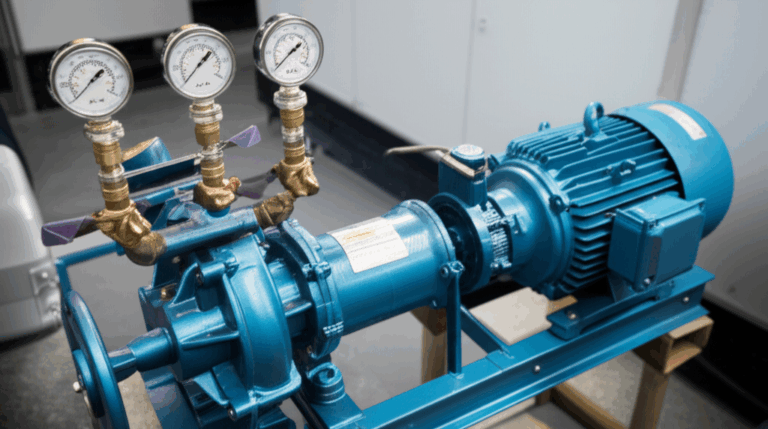
Let’s call out the elephant in the room. As motors become the heartbeat of everything from electric vehicles to wind turbines, stator and rotor quality determines whether your product hums quietly or grinds to a costly halt. These parts are the working duo that converts magnetic energy into real mechanical power. Even the slightest deviation in their geometry, composition, or assembly can mean lower efficiency, excess heat, and early failure.
For engineers, product designers, and procurement managers alike, the stakes are high:
- Designers struggle to see how small design tweaks play out in real production.
- Manufacturers wrestle with quality control at scale—catching errors before they become expensive scrap.
- Managers chase traceability, striving to link a single defective part back to its origin.
Digital twin technology aims to solve these headaches by tying everything—CAD geometry, FEA predictions, and actual QC measurements—into a single, dynamic, data-driven model of your motor’s stator and rotor components.
Engineering Fundamentals: What Makes a Digital Twin Work?
A digital twin isn’t just a fancy 3D model. It’s a living, breathing digital representation that mirrors the physical motor part as it moves through design, manufacturing, and field use. But what does that really mean?
Breaking Down the Simplicity
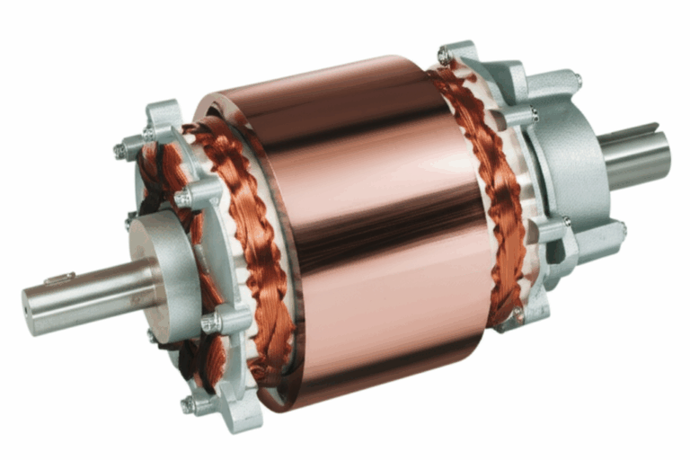
Think of your stator or rotor as an athlete.
- The CAD model is the athlete’s blueprint—bone structure and muscles.
- FEA (Finite Element Analysis) data is like a stress test—predicting how the athlete will perform under pressure.
- QC (Quality Control) data is the health check, assessing if the athlete’s actual body matches the planned structure, catching any injuries or irregularities.
When you connect these three, you get a complete picture: not just how the part should look and behave, but how it actually performs as it rolls through the factory and lands in the field.
Key Terminology—Explained Simply
- CAD (Computer-Aided Design): This is the geometric foundation. Think parametric 3D models that precisely define every nook and cranny of your lamination stack—crucial for interoperability and downstream checks.
- FEA (Finite Element Analysis): Here’s where you put your design to the test. By simulating electromagnetic, thermal, or structural forces, you can predict how material choices and geometry affect efficiency and performance.
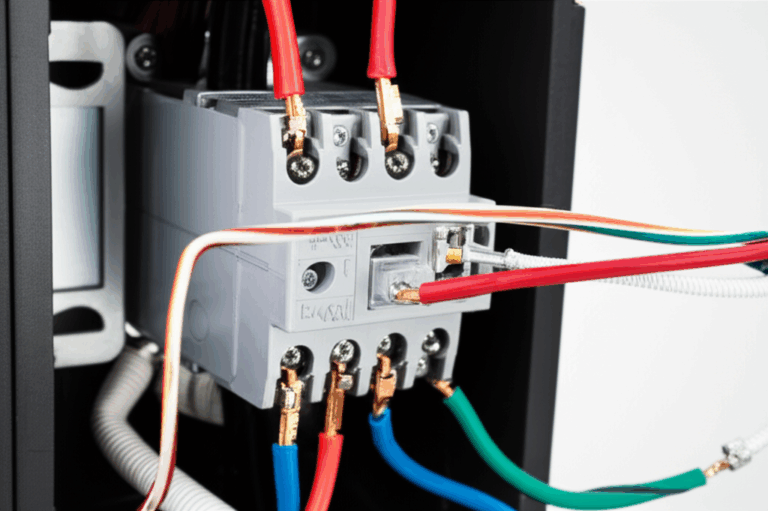
- QC (Quality Control) Data: This is real-world feedback—measurements from CMMs (coordinate measuring machines), 3D scans, or even X-ray inspections that tell you if the part you made matches the plan.
Analogy Time: Imagine building a ship. CAD is your blueprint, FEA simulates how your hull will handle rough seas, and QC is the checklist confirming you actually built what you drew and designed—down to the last bolt.
Guide to Material Choices and Manufacturing for Laminations
Deciding which materials and processes to use for your stator and rotor laminations is like picking the right running shoes for a marathon—it can make or break performance.
Material Considerations
Silicon Steels (M-grades)
- When to Use: Your go-to for general-purpose motors and transformers. It’s the industry’s bread and butter for its balance of properties.
- Pros: Readily available, cost-effective, solid electromagnetic performance at 50-60 Hz.
- Cons: At very high frequencies (like in some EV or spindle motors), losses increase, and efficiency drops.
Cobalt Alloys
- When to Use: High-frequency, high-power-density applications—think aerospace or specialty high-efficiency motors.
- Pros: Lower core losses at high frequencies, greater saturation flux density.
- Cons: Much pricier and can be harder to work with during stamping or bonding.
Amorphous & Nanocrystalline Materials
- When to Use: Ultra-high-efficiency designs, such as premium transformer cores or high-speed motors.
- Pros: Outstanding loss reduction.
- Cons: Brittle and expensive—challenging to stamp or stack without cracking.
Grain Oriented & Non-Oriented Steels
- Oriented Steels (CRGO): Ideal for transformer cores that need low core loss in a single direction.
- Non-Oriented Steels (CRNGO): Better for motors where the magnetic field rotates.
Side note: Don’t overlook insulation coatings. Properly applied, these create a barrier that blocks unwanted eddy currents—just like how thermal socks prevent heat loss from your feet.
If you’re interested in a deeper dive into the best electrical steels, check out this guide on electrical steel laminations.
Manufacturing & Assembly Techniques
Motor core laminations are all about repeatability, precision, and scale. How you make them changes outcomes—sometimes drastically.
Stamping
- Description: The most common for high-volume, simple shapes. Like a cookie cutter for metal sheets.
- Pros: Fast, consistent, and cost-effective for big runs.
- Cons: Die wear and burr formation if not maintained. Design limitations for intricate geometries.
Laser Cutting
- Description: Perfect for prototypes or lower volume, complex designs.
- Pros: Extreme flexibility, minimal tooling costs, great for odd-shaped slots or holes.
- Cons: Slower per part, can introduce heat-affected zones, sometimes not ideal for mass production.
Bonding & Welding
- Bonding (with adhesives) can produce stronger, quieter stacks (think: gluing LEGO® bricks), but it adds a step.
- Welding is fast, but the heat can degrade magnetic properties at the join.
Interlocking
- Mechanical tabs or notches lock laminations together—much like building with LEGO®.
- Ideal when you want to skip adhesives or welding, preserving material integrity.
For more about these processes, visit motor core laminations.
Key Tip: Always balance speed, cost, and performance requirements. The best method isn’t always the fanciest—it’s the one that matches your goals.
Crafting the Digital Thread: Connecting CAD, FEA, and QC Data
Now, let’s get into the heart of the digital twin: weaving all your design, simulation, and quality data into one, robust digital thread.
Establishing Data Interoperability
If you’ve ever tried getting a CAD file to play nicely with a simulation tool from another vendor, you know the pain of data silos. Manufacturers juggle data stored in different formats, locked away in proprietary systems, or passed hand-to-hand in spreadsheets. It’s not only inefficient—it’s a breeding ground for errors.
Solution: Use open, standardized data formats like STEP or IGES for geometry, and build APIs to connect CAD, FEA, and QC systems. Product Lifecycle Management (PLM) platforms (e.g., Siemens, Dassault Systèmes, PTC) are becoming standard issue—think of them as the digital “glue” that links design and quality data across your organization.
Real-Time Data Capture on the Factory Floor
Deploying IoT sensors and high-speed optical scanning isn’t future tech anymore—it’s happening every day. By embedding sensors on stamping presses or using automated 3D optical inspection, you can pipe live QC data directly into your digital twin.
For example: A large motor manufacturer achieved a remarkable 15–25% reduction in scrap and rework costs just by integrating real-time QC feedback from 3D scanners into their manufacturing process (see the Deloitte Industry 4.0 study, 2023).
Closing the Loop with AI and Machine Learning
This is where digital twins get really smart. Imagine detecting a subtle shift in lamination geometry after a tool change—before it cascades into a pile of rejects. Machine learning algorithms can flag these deviations, triggering process adjustments or suggesting design tweaks.
Analogy: It’s like having a digital personal trainer spotting form flaws before you injure yourself, rather than realizing the problem months down the road.
If you need examples and implementation tips, you’ll find great resources under core lamination stacks.
Choosing Manufacturing Techniques: Pros, Cons, and Best Fits
No two applications are the same. Let’s break down which solutions fit best—and where.
Stamping vs. Laser Cutting
Stamping:
- Best for: High-volume, simple or slightly complex shapes.
- Watch out for: Tooling investment is high up front, but it pays for itself at scale.
- Common in: Mass-produced induction motors, automotive drive motors.
Laser Cutting:
- Best for: Prototyping, R&D, limited runs, or intricate geometry that stamping can’t touch.
- Downside: Not always economically viable at scale.
Assembling Laminations—Interlocking, Welding, or Bonding?
- Interlocking: Zero heat damage, mechanical integrity, great for moderate volumes.
- Welding: Fast but can degrade edge magnetic properties—mind the HAZ (heat-affected zone).
- Bonding: Superior noise and vibration dampening, usually with coated adhesives.
Curious about advanced stator options? Take a closer look at stator core lamination.
Future Fit: Overcoming Hurdles and Unlocking New Opportunities
Challenges: Data, Security, and Skills
Next-Gen Digital Twins: Self-Optimizing Manufacturing
The future is heading toward autonomous digital twins: models that not only monitor and predict, but actively correct manufacturing processes in real time. Think “smart factory” meets closed-loop control—the system catches a stator geometry drift, self-adjusts tool paths, and alerts engineers before it becomes a warranty issue.
Your Key Takeaways and Next Steps
Let’s wrap with straightforward, actionable points:
What You Need to Remember
- Digital twins tie together CAD, FEA, and QC data, giving you a living picture of your stator and rotor parts—across the entire product lifecycle.
- Material and manufacturing method choices define everything from performance to profit margin—silicon steels for general use, cobalt alloys for high performance, and a careful eye on insulation and assembly technique.
- PLM and MES platforms are your allies in building the “digital thread” that connects design, simulation, and real-world results.
- AI-driven analytics and real-time QC feedback slash scrap, speed up time-to-market, and keep defects from slipping through.
- Investing in data interoperability and workforce development pays off, ensuring your digital twin strategy actually delivers ROI—increased yields, reduced downtime, and traceable, high-quality products.
Ready to Move Forward?
If you’re starting your digital twin journey, empower your team to gather a cross-functional taskforce—designers, quality engineers, factory floor managers. Map your data flows. Pinpoint pain spots (typically, file incompatibility or manual data entry). Consider piloting a digital twin approach on a single stator or rotor component and benchmark the results.
And remember: Collaboration with trusted engineering partners—and suppliers with proven digital twin expertise—can accelerate your path to success.