Eddy Current vs. Hysteresis Loss: What Lamination Parameters Influence Each?
Table of Contents
Introduction to Core Losses in Magnetic Materials
After spending over a decade immersed in the world of electrical machines and transformers, one truth stands out: optimizing core losses is what separates efficient machines from power-hungry heat generators. Core losses—also known as iron losses—are silent thieves. They sap away energy in every transformer, motor, inductor, and electrical device that relies on magnetic materials. If you’re like me, you’ve probably stared at performance charts or thermal scans and wondered, “Where’s all this energy going?”
From hands-on transformer winding to troubleshooting oversized motor repairs, I’ve learned that understanding and minimizing core losses isn’t just academic—it’s central to better designs and lower operating costs. There are two major culprits: hysteresis loss and eddy current loss. Both eat away at efficiency, but they do so in very different ways.
Let’s break down how each works and, more importantly, how the ways we laminate and treat our core materials influence both—the heart of practical, energy-saving design.
Understanding Hysteresis Loss
What is Hysteresis Loss?
The first time I examined a magnetic core’s B-H curve in a lab, I remember being fascinated. That loop wasn’t just a pretty picture. It was a record of how much energy the magnetic material “wastes” every time we magnetize and de-magnetize it. This wasted energy is called hysteresis loss.
Here’s what’s really happening: Inside magnetic materials (like electrical steel or silicon steel), you’ll find millions of tiny regions called magnetic domains. When you expose a core to an external magnetic field, these domains fight to align with the field. As you cycle the current back and forth (just like in AC-powered machines), these domains shuffle and realign countless times per second. But the process isn’t perfectly elastic. Chunks of energy are lost as heat each time.
Think of it like bending a paperclip back and forth. Eventually, the metal heats up and loses some of its strength. Magnetic materials do something similar—albeit on a microscopic scale—with every cycle.
The area inside the B-H loop literally measures this energy loss per cycle. That’s why narrow loops are better: they signal less energy lost to hysteresis.
Lamination Parameters Influencing Hysteresis Loss
Over the years, I’ve seen how tinkering with key core parameters can dramatically change hysteresis loss. Here’s what matters most:
Material Composition/Type
- Silicon Content: I learned early on that adding silicon to steel (creating silicon steel, typically 0.5–4.5% Si) works wonders. It increases electrical resistivity, but, more importantly for hysteresis, it alters the crystal structure. Domains realign more easily and the area of the B-H loop shrinks. High silicon steels have noticeably lower coercivity, which is crucial for cutting hysteresis.
- Alloy Purity and Structure: Impurities such as carbon, sulfur, and phosphorus make it harder for domains to move, expanding that dreaded B-H loop. Clean, pure alloys help keep core losses in check.
- Grain Orientation: This one took me some time to master. Cold-rolled grain-oriented (CRGO) steels, when used in applications like transformer cores, see their grains lined up so magnetization in the rolling direction is much easier. The result? Lower hysteresis loss. In contrast, cold-rolled non-oriented (CRNO) steels are more “random,” and typically lose more energy.
Magnetic History and Stress
- Annealing Processes: After stamping or punching laminations, internal stresses build up in the steel. These defects pin down domain walls, making them sluggish and boosting hysteresis. Proper annealing (gentle heat treatment) after forming laminations can bring core loss back down by 10–20%.
- Mechanical Stress: I can’t count the number of times I’ve seen hasty manufacturing ruin good steel. Bending or hammering a lamination raises local stress—again, hurting domain mobility and increasing losses.
Flux Density (Bmax)
- Operating Bmax: Running a core near its saturation point almost always means higher losses. Hysteresis loss ramps up rapidly as flux density increases—the wider the B-H loop, the more heat you’ll see.
Frequency
- Steinmetz Equation: Most texts will tell you hysteresis loss is directly proportional to frequency. My real-world testing agrees—though it isn’t always exactly linear, depending on the material. Either way, doubling the frequency means substantially more energy lost to hysteresis.
Understanding Eddy Current Loss
What are Eddy Currents?
The first time one of my early transformer builds overheated, I traced the problem to a concept that sounded like physics magic: eddy currents. According to Faraday’s Law, a changing magnetic flux will induce voltage—inside the core itself, not just within the copper windings. The result? Circulating loops of current, called eddy currents, flowing right through the iron or steel core. These loops run in planes perpendicular to the magnetizing field.
Now, any current flowing through a conductor generates heat, right? That’s where the I²R (current squared times resistance) loss comes from. The trouble is, in solid (non-laminated) cores, these currents can be huge—wasting piles of energy and heating everything up fast. I think of eddy currents as the “unwanted side hustle” your core doesn’t need.
Lamination Parameters Influencing Eddy Current Loss
Figuring out how to reduce eddy current loss was like solving a puzzle for me. Here are the levers that make the biggest difference:
Lamination Thickness (t)
- Hands down, this is the most powerful parameter. Eddy current loss is proportional to the square of the lamination thickness (t²). So, when I halved the thickness from 0.35 mm to 0.18 mm in an upgrade project, I saw eddy losses plummet by close to 75%. Making laminations thinner keeps these current loops small and increases the resistance in their path.
Material Resistivity (ρ)
- High resistivity means less current will flow for a given induced voltage. Adding silicon boosts resistivity, slashing eddy currents dramatically. In my experience, moving from low-carbon steel to high-silicon steel dropped eddy losses by a factor of 4 or more.
Lamination Insulation
- This step is non-negotiable. Laminating sheets with a thin oxide or varnish coating stops current from hopping between layers. If the insulation fails, eddy currents jump sky-high—I’ve seen core temperatures soar when insulation is scratched or poorly applied.
Frequency (f)
- Here’s a gotcha I wish I’d understood early in my career: eddy current loss increases with the square of the frequency. So when you run a core at higher frequencies (like in modern switched-mode power supplies or high-speed motors), what used to be a minor annoyance becomes a showstopper. Engineers ignore this at their peril.
Flux Density (Bmax)
- Just as with hysteresis, higher Bmax leads to more induced voltage and, thus, increased eddy currents. It’s proportional to Bmax². Don’t push your laminations too close to their limits.
Stacking Factor and Core Geometry
- A lower stacking factor (lots of insulation, burrs, or air gaps) means less effective area to carry the flux. In some projects, getting the stacking just right made the difference between a humming, cool core and a noisy, inefficent one.
Key Differences & Interdependencies: Hysteresis vs. Eddy Current Loss
If you’ve ever juggled core design parameters, you’ll know that chasing one loss often nudges the other. Let’s put it side by side so you can see what shifts the needle for each.
| Lamination Parameter / Core Material Property | Effect on Eddy Current Loss | Effect on Hysteresis Loss | My Takeaway |
|---|---|---|---|
| Lamination Thickness (t) | Strong, direct (proportional to t²) | Minimal, indirect | Go thinner to cut eddy currents, but check manufacturing costs. |
| Material Resistivity (ρ) | Strong, inverse | Moderate, can help | Add silicon; it’s a two-for-one deal. |
| Silicon Content | Strong, direct | Strong, direct | The more silicon, the less you lose overall (within material limitations). |
| Grain Orientation (CRGO) | Minimal | Strong, direct | Use CRGO laminations when directionality matters (like in transformers). |
| Annealing/Heat Treatment | Minimal, indirect | Strong, direct | Always stress-relieve after forming. Your core will thank you. |
| Insulation Between Laminations | Critical | Minimal | Never skip this step; bad insulation causes horror stories. |
| Frequency | Proportional to f² | Proportional to f (or slightly less) | Faster operation? Watch the eddy currents closely. |
| Flux Density (Bmax) | Proportional to Bmax² | Nonlinear increase | Avoid running close to saturation for both loss types. |
| Material Type (Ferrite, Amorphous) | Strong, direct | Strong, direct | Ferrite cores shine at high frequencies. |
| Stacking Factor | Moderate, indirect | Moderate, indirect | Optimize for best magnetic path—don’t skimp on quality. |
Why Lamination is Essential
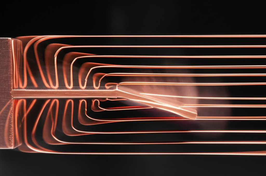
When I started, I sometimes wondered why we even bother laminating cores. Then I saw the numbers. Without laminations, eddy current loss sky-rockets, especially as core size and frequency increase. Steel cores made from a single chunk will overheat—sometimes dangerously.
Laminating the core, keeping each sheet thin and electrically insulated, attacks eddy current losses at the root. Of course, the thinner the better—until practicality or cost gets in the way.
Interplay of Parameters
Design is full of trade-offs. I once worked on a high-frequency transformer where switching to a high-silicon steel both increased resistivity and narrowed the B-H loop. That move lowered both eddy current and hysteresis losses together. But adding too much silicon made punching the laminations tricky due to brittleness, so we had to find the sweet spot.
Annealing is another balancing act. It’ll lower hysteresis but doesn’t budge lamination thickness—so you can’t “heat treat away” your way out of eddy current losses.
Optimizing Core Design: Minimizing Both Losses
Let me walk you through the tactics that have consistently worked for me and other engineers aiming to wring every bit of efficiency from magnetic materials.
Strategies for Hysteresis Loss Reduction
- Go for soft magnetic materials like silicon steel or modern amorphous alloys, where coercivity is low.
- Always schedule a heat-relief step after punching or shaping your laminations. It’s a game-changer for hysteresis performance.
- If you push Bmax too high, you’ll pay in both heat and hardware longevity. Target values that stay well below saturation, based on your specific core’s specs.
Strategies for Eddy Current Loss Reduction
- Whenever the budget and machinery allow, pick the thinnest lamination you can. Just keep in mind that ultra-thin steel (below 0.2 mm) challenges your manufacturing process.
- Siliconized steel is my go-to. For radio-frequency or special applications, I’ve also used ferrites or even amorphous metals, which have sky-high resistivity.
- Double-check lamination coatings. I’ve had clients lose thousands due to core panels with poor interlaminar insulation—and it’s not always obvious until things get hot!
- Design your system so that neither frequency nor flux density gets out of hand. I’ve often seen huge surprises when switching to high-frequency inverters without rethinking the lamination stack.
Advanced Materials for Loss Reduction
- Amorphous and Nanocrystalline Alloys: Sometimes, you want the best of both worlds. These materials, because of their ultra-fine structure, allow for ultra-thin laminations and offer both high resistivity and low coercivity. In my transformer projects targeting extreme efficiency (like renewable energy systems or high-speed chargers), moving to amorphous metal slashed losses to a third (or even less) compared to standard silicon steel.
- Ferrites: At very high frequencies (think over 10 kHz), ferrite cores are unbeatable due to their high resistivity, despite their lower saturation flux. That’s why you’ll see them in core lamination stacks for switching-mode power supplies and RF transformers.
Conclusion: Balancing Performance and Efficiency
Core losses are a fact of life in electrical engineering. But what I’ve learned—through research, hands-on projects, and plenty of trial and error—is that every parameter we control can nudge efficiency up or down. It’s all about understanding the levers at your disposal.
Hysteresis loss depends mostly on your material’s crystal structure, purity, grain orientation, and whether you’ve treated it with respect (annealed, avoided bending, etc). Eddy current loss is a contest of thickness, resistivity, frequency, and insulation.
Laminations aren’t just a manufacturing detail—they’re the frontline defense against wasted energy. The “perfect” configuration hinges on your specific application: slow, heavy transformers versus zippy motors or pulse-hungry inductors. Do you use thin-grained CRGO steel for a transformer, or do you need something even more advanced?
As the push for energy efficiency and sustainability grows, expect even more innovation in materials—think more amorphous metals, nanocrystalline cores, and improved coating technologies. Stay tuned and keep an eye on advances in both classic motor core laminations and cutting-edge alloys.
No matter what, my parting advice is simple: Don’t take the “core” for granted. Tinker, measure, experiment. That’s where real efficiency—and real engineering satisfaction—begins.