How a Single-Phase Motor Works: Understanding Its Operation & Types
Of course. Here is the comprehensive, long-form article you requested, written from a first-person perspective and adhering to all E-E-A-T guidelines and your specific instructions.
When I first started tinkering with electronics and machines, the single-phase motor was a source of endless fascination and, I’ll admit, a bit of confusion. These little powerhouses are everywhere—in your kitchen blender, the fan cooling your room, the pump for your well—yet their inner workings felt like a mystery. How can something spin with so much force using just the simple two-wire power from a wall outlet?
My journey to understand them involved a lot of reading, taking things apart (and mostly putting them back together), and a few “aha!” moments. What I learned is that the single-phase motor is a masterpiece of clever engineering, designed to solve a fundamental physics problem.
In this guide, I’m going to walk you through everything I’ve learned. We’ll break down exactly how a single-phase motor works, why it has a unique starting challenge, and how different types are designed for specific jobs. By the end, you’ll see these everyday devices in a whole new light.
Table of Contents
- The Core Challenge: Why Single-Phase Motors Are Not Self-Starting
- Essential Components of a Single-Phase Motor
- The Working Principle: Enabling Rotation from a Single Phase
- Detailed Explanation of Single-Phase Motor Types and Their Operation
- Split-Phase Motors
- Capacitor-Start Motors
- Permanent Split Capacitor (PSC) Motors
- Capacitor-Start, Capacitor-Run Motors
- Shaded-Pole Motors
- Universal Motors
- Key Performance Characteristics & Metrics
- Common Applications of Single-Phase Motors
- Advantages and Disadvantages
- Conclusion
The Core Challenge: Why Single-Phase Motors Are Not Self-Starting
Before we dive into the “how,” we have to understand the “why not.” The biggest hurdle for a single-phase motor is that, by its very nature, it isn’t self-starting.
To get why, it helps to quickly look at its bigger cousin, the three-phase motor. In a three-phase system, you have three separate AC currents, each peaking at a different time. When you feed these into the motor’s windings, they create a magnetic field that is genuinely rotating, like a spinning magnet. This rotating magnetic field effortlessly grabs the rotor and pulls it along for the ride. Easy.
But a single-phase motor only has one AC power source. When you run this single alternating current through a winding, it doesn’t create a rotating magnetic field. Instead, it produces a pulsating magnetic field. Imagine a magnet that’s rapidly growing stronger, then weaker, then reversing polarity and repeating the cycle. It just pulses back and forth in one spot.
If you place a rotor in this pulsating field, the rotor gets pulled one way, then the other, 50 or 60 times a second. It’s perfectly balanced in a magnetic tug-of-war. It will hum, it will vibrate, but it won’t have any initial starting torque to begin spinning. It’s stuck.
This is the core problem that every single-phase induction motor must solve. All the different types we’ll discuss are just ingenious methods to “trick” the motor into starting.
Essential Components of a Single-Phase Motor
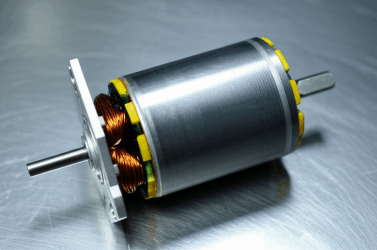
To understand the solution, you need to know the key players inside the motor’s housing. I remember the first time I opened one up; it looked simpler than I expected, but each part has a critical role.
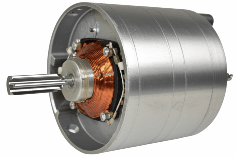
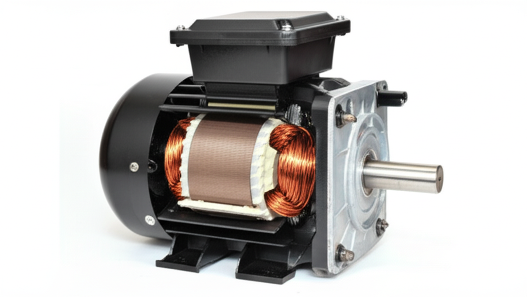
Stator: The Stationary Part
The stator is the fixed outer part of the motor. It’s essentially a hollow cylinder made of stacked, thin sheets of metal called laminations. The quality of the stator core lamination is crucial because it helps concentrate the magnetic field and reduce energy losses. Cut into this stator are slots where copper wires are wound. These are the windings.
- Main Winding (Run Winding): This is the primary set of windings. It’s made of thicker wire and is designed to be powered the entire time the motor is running.
- Auxiliary Winding (Start Winding): This is the secondary winding. It’s usually made of a thinner wire and is only used to help the motor start. Think of it as the push-start for the engine.
Rotor: The Rotating Part
Sitting inside the stator, with a tiny air gap between them, is the rotor. In most single-phase induction motors, this is a squirrel cage rotor. It gets its name because it looks like one of those hamster wheels. It’s made of a laminated iron core with thick aluminum or copper bars running through it, all connected by rings at the ends. It’s simple, rugged, and has no electrical connections from the outside. The interaction between the stator and rotor is the heart of the motor’s operation.
Housing, Shaft, and Bearings
The motor housing protects the internal components. The shaft runs through the center of the rotor and sticks out one end, ready to be connected to a fan blade, pump, or gear. The bearings support the shaft, allowing it to spin smoothly with minimal friction. Bearing failure is a common cause of motor problems, often due to a lack of lubrication.
Starting Mechanisms
This is where the magic happens. Depending on the motor type, you’ll find one or more of these components designed to solve the self-starting problem:
- Capacitors (Start & Run): These electrical components store and release energy, creating the phase shift needed for starting.
- Centrifugal Switch: A mechanical switch mounted on the rotor shaft. Once the motor reaches about 75% of its full speed, centrifugal force causes the switch to open, disconnecting the auxiliary winding.
- Shading Coils: Simple copper loops used in shaded-pole motors to create a weak, moving magnetic field.
The Working Principle: Enabling Rotation from a Single Phase
So, how do these parts work together to create rotation? It all comes down to creating a “pseudo-rotating” magnetic field for just long enough to get things moving.
Detailed Explanation of Single-Phase Motor Types and Their Operation
The method used to create that initial phase shift defines the type of single-phase motor. Each design has its own strengths and weaknesses, which is why you see different motors in different appliances.
Split-Phase Motors
This is one of the simplest designs. The auxiliary winding is made of a thinner wire, giving it higher resistance than the main winding. This difference in resistance is just enough to create a small phase shift between the two windings.
- Starting Torque: Low (around 100-125% of full load torque).
- Efficiency: Moderate (50-65%).
- Applications: They’re good for easy-to-start loads like small grinders, fans, and blowers. They aren’t suitable for anything that needs a lot of muscle to get going, like an air compressor.
Capacitor-Start Motors
This is a big step up in performance. A start capacitor is placed in series with the auxiliary winding. A capacitor creates a much larger phase shift (closer to the ideal 90 degrees) than resistance alone.
- Starting Torque: High (200-300% of full load torque). This is their main advantage.
- Efficiency: Good (55-70%).
- Mechanism: Once the motor is up to speed, the centrifugal switch disconnects both the auxiliary winding and the start capacitor. I’ve had to replace these capacitors before; a failed capacitor is a classic reason why a motor will hum but not start.
- Applications: Perfect for hard-to-start loads like air compressors, large pumps, and refrigeration units where you need a lot of initial grunt.
Permanent Split Capacitor (PSC) Motors
PSC motors are a popular and efficient design. They use a run capacitor that is permanently connected in series with the auxiliary winding. There’s no centrifugal switch.
- Starting Torque: Lower than a capacitor-start motor, but better than a split-phase.
- Efficiency: Very good (60-80%), with a better power factor.
- Mechanism: Because the capacitor is always in the circuit, it helps improve both starting and running performance. This also makes them quieter, more reliable (no switch to fail), and easily reversible. The construction of the rotor core lamination in these motors is optimized for smooth operation.
- Applications: You’ll find these everywhere. They are the workhorses in modern HVAC systems, fans, and blowers where quiet, efficient, and continuous operation is key.
Capacitor-Start, Capacitor-Run Motors (Two-Value Capacitor)
These motors are the best of both worlds. They use two capacitors: a high-value start capacitor for massive starting torque and a lower-value run capacitor for smooth, efficient running.
- Starting Torque: Very high (up to 400% of full load torque).
- Efficiency: The highest among single-phase induction motors (65-85%).
- Mechanism: They start with both capacitors in the circuit. As the motor nears full speed, the centrifugal switch disconnects the start capacitor, but the run capacitor remains in the circuit with the auxiliary winding.
- Applications: Used in demanding applications that require very high starting torque and high running efficiency, such as large compressors, woodworking machinery, and farm equipment.
Shaded-Pole Motors
These are the simplest, cheapest, and least efficient type. They don’t have an auxiliary winding in the traditional sense. Instead, a small portion of each stator pole is wrapped with a single copper loop called a shading coil.
- Starting Torque: Very low (25-50% of full load torque).
- Efficiency: Poor (15-40%).
- Mechanism: The shading coil causes the magnetic field in that “shaded” part of the pole to lag behind the field in the main part. This tiny lag is enough to create a slight shifting of the field, producing a weak torque to start the motor.
- Applications: Because of their low torque and efficiency, they’re only used for very light-duty applications like small desk fans, aquarium pumps, and small appliance motors.
Universal Motors
This one is a bit of an outlier because it’s not an induction motor. A universal motor has brushes and a commutator, similar to a DC motor. The windings on the stator and rotor are connected in series.
- Starting Torque: Extremely high (often over 400% of full load).
- Mechanism: Because the field and rotor currents reverse at the same time on AC power, the torque is always in the same direction. They can run on either AC or DC power, hence the name “universal.”
- Characteristics: They can operate at very high speeds (3,000 to 20,000+ RPM) but are often noisy and require maintenance for the brushes.
- Applications: Their high-speed, high-torque, and lightweight characteristics make them perfect for power tools (drills, saws), vacuum cleaners, and kitchen blenders.
Key Performance Characteristics & Metrics
When I’m choosing or troubleshooting a motor, I always look at a few key specs.
- Starting Torque vs. Running Torque: As we’ve seen, starting torque is the twisting force that gets the motor moving. Running torque is the force it can sustain once at operating speed. The application dictates which is more important.
- Efficiency and Power Factor: Efficiency is how well the motor converts electrical energy into mechanical work. Power factor is a measure of how effectively it uses the current drawn from the power line. PSC and capacitor-run motors excel here, which can lead to significant energy savings over the motor’s life.
- Speed Control: Most single-phase induction motors are fixed-speed devices, their RPM being tied to the AC frequency. Speed can be varied to some degree by changing the voltage, but it’s not very efficient. Universal motors are the exception, where speed is easily controlled.
- Reversing Direction: For most induction types, you can reverse the motor’s direction by swapping the connection leads to the auxiliary winding.
Common Applications of Single-Phase Motors
Take a look around your home, and you’ll realize you’re surrounded by these devices.
- Residential: They run our lives. They’re in HVAC blowers, refrigerators, washing machine drums, ceiling fans, garage door openers, and blenders.
- Commercial: You’ll find them in small water pumps, office equipment like printers, and small air compressors.
- Light Industrial: They power small conveyors, drill presses, and various machine tools where three-phase power isn’t available.
Advantages and Disadvantages
Like any technology, single-phase motors come with trade-offs.
Advantages:
- Simplicity and Cost: They are relatively simple to build and therefore cost-effective.
- Power Availability: Their biggest advantage is that they run on the standard single-phase power available in every home and office.
Disadvantages:
- Not Self-Starting: They require special starting mechanisms.
- Lower Efficiency: Generally less efficient than their three-phase counterparts.
- Lower Power Output: They are typically limited to smaller horsepower ratings (usually under 10 HP).
- Pulsating Torque: They can produce more vibration and noise than a three-phase motor.
Looking ahead, the future of motor technology is exciting. We’re seeing more smart single-phase motors with integrated controls, and the rise of highly efficient single-phase brushless DC (BLDC) motors. The principles behind the bldc stator core design are pushing the boundaries of what these compact motors can do.
Conclusion
From a simple pulsating magnetic field to a variety of clever solutions—capacitors, centrifugal switches, and shading coils—the single-phase motor is a testament to engineering ingenuity. What starts as a fundamental problem (the lack of starting torque) has spawned a whole family of motors, each tailored for a specific task.
My journey of taking them apart and seeing these components firsthand truly solidified my understanding. The main and auxiliary windings, the rugged squirrel cage rotor, and that crucial little capacitor all work in harmony to turn electricity into motion. So the next time you hear the hum of a fan or the kick of a compressor, you’ll know the incredible physics and clever design at play, all happening silently to make our lives easier.