How Does a Squirrel Cage Motor Work?
Table of Contents
- Introduction to Squirrel Cage Induction Motors
- Key Components of a Squirrel Cage Motor
- The Stator
- The Rotor (The “Squirrel Cage”)
- The Air Gap
- Supporting Components
- The Working Principle: Step-by-Step Explanation
- Step 1: Creating the Rotating Magnetic Field (RMF) in the Stator
- Step 2: Inducing Current in the Rotor Bars (Faraday’s Law)
- Step 3: Generating Rotor Current and its Own Magnetic Field (Lenz’s Law)
- Step 4: Producing Torque and Rotation (Lorentz Force)
- Step 5: Understanding “Slip” for Continuous Operation
- Advantages of Squirrel Cage Motors
- Disadvantages and Limitations
- Common Applications of Squirrel Cage Motors
- Conclusion: The Unsung Hero of Modern Industry
Introduction to Squirrel Cage Induction Motors
When I first started my journey in the world of electrical machinery, I was surrounded by dozens of different motor types. It was overwhelming. But one name kept popping up everywhere, from the giant fans cooling the factory floor to the pumps moving thousands of gallons of water: the squirrel cage motor. For a long time, I just accepted that they worked. You give them power they turn. Simple.
But to truly understand the machines I was working on, I knew I had to go deeper. What was actually happening inside that simple metal frame? How could something with no brushes, no direct electrical connection to its rotating part, create so much power? The answer, I discovered, is a beautiful dance of physics that’s both elegant and incredibly robust.
So, what is a squirrel cage motor? At its heart, it’s a type of AC induction motor. An induction motor works on the principle of electromagnetic induction, meaning it uses a magnetic field to “induce” a current in its rotating part, which then creates motion. There’s no physical electrical contact needed for the magic to happen.
And why the funny name? If you were to strip away the outer steel core of the motor’s rotor, you’d be left with a cylindrical cage of conductive bars, shorted out at each end by a ring. It looks strikingly similar to the exercise wheel you might find in a hamster or squirrel cage. It’s a simple, brilliant design that has barely changed in over a century, and it’s the reason these motors are the workhorses of modern industry, accounting for an estimated 80-90% of all industrial motors globally. They’re reliable, cheap to make, and they just keep running. Let’s break down how they do it.
Key Components of a Squirrel Cage Motor
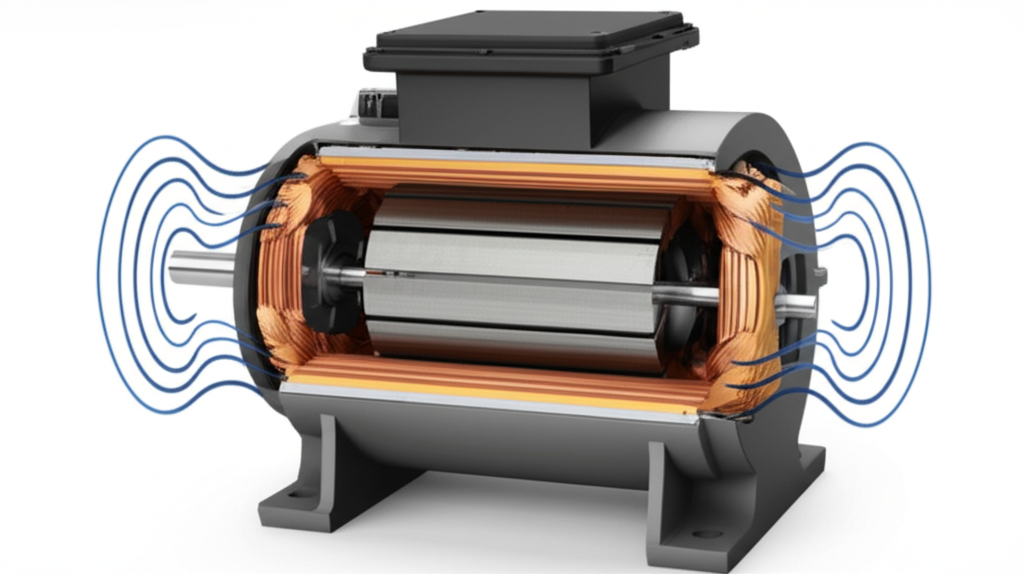
Before we can get into the how, we need to understand the what. A squirrel cage motor seems like a black box from the outside, but its anatomy is surprisingly straightforward. I’ve taken apart more of these than I can count and the core parts are always the same. Broadly speaking, every motor is about the relationship between the stator and rotor, and the squirrel cage motor is a perfect example of this.
The Stator
The stator is the stationary part of the motor—it doesn’t move. Think of it as the house that everything else lives in. It has two main parts that matter to us:
- Laminated Core: The stator isn’t a solid block of steel. Instead, it’s made of very thin, stacked steel plates called laminations. When I first saw one, I wondered why they went to all that trouble. The reason is to fight against something called “eddy currents.” These are wasteful little circular currents that get induced in the core by the changing magnetic field. They generate heat and reduce efficiency. By using a high-quality stator core lamination, manufacturers can dramatically cut down on these losses, making the motor more efficient.
- Stator Windings: Tucked into slots within this laminated core are coils of insulated copper wire. These are the stator windings. For a three-phase motor, the most common type in industrial settings, there will be three sets of windings. These windings are where the magic begins. When you connect them to an AC power supply, they produce the all-important rotating magnetic field.
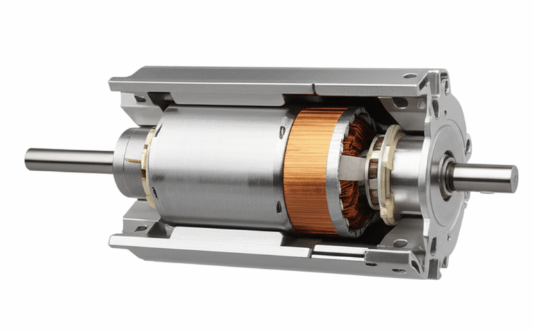
The Rotor (The “Squirrel Cage”)
Now for the moving part. The rotor is what spins and is connected to the shaft, which delivers the mechanical work to drive a pump, fan, or conveyor belt. Just like the stator, its core is also made of stacked steel laminations to minimize energy losses.
- Rotor Bars: Embedded within the rotor core are thick bars, usually made of aluminum or copper. These aren’t wires like in the stator; they are solid, sturdy conductors.
- End Rings: At each end of the rotor, all the rotor bars are connected by a solid conductive ring. This is what shorts them all together, creating a closed electrical circuit. The combination of the bars and the end rings is what forms the “squirrel cage.” It’s a self-contained, incredibly rugged electrical circuit with no external connections.
- Shaft: The shaft is the steel rod that runs through the center of the rotor. It’s mounted on bearings and extends out of the motor’s frame so you can connect it to a load.
The Air Gap
This isn’t a physical part, but it’s one of the most critical elements in any motor’s design. The air gap is the tiny, precise space between the stationary stator and the spinning rotor. This gap has to be as small as possible without the two parts touching. Why? Because the magnetic field created by the stator has to jump across this gap to interact with the rotor. The bigger the gap, the more power you need to create a strong enough field, which makes the motor less efficient. Getting this gap right is a huge part of motor manufacturing.
Supporting Components
Of course, there are other parts that hold everything together and keep it running smoothly:
- Bearings: These support the shaft at both ends, allowing it to spin freely with minimal friction. In my experience, bearing failure is one of the most common reasons a motor needs repair, so good maintenance here is key.
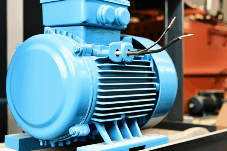
- Frame/Enclosure: This is the motor’s outer shell, which protects the internal components from dust, moisture, and physical damage.
- Cooling Fan: Most squirrel cage motors have a fan attached to the shaft at the back. As the motor spins, the fan blows air over the finned frame, dissipating the heat generated during operation.
- Terminal Box: This is where you connect the electrical power supply to the stator windings.
The Working Principle: Step-by-Step Explanation
Okay, we know the parts. Now, how do they all work together to create motion? The general motor principle is about converting electrical energy into mechanical energy and here’s how I learned to visualize it, step-by-step.
Step 1: Creating the Rotating Magnetic Field (RMF) in the Stator
Everything starts when you connect a three-phase AC power supply to the stator windings. AC power isn’t a constant flow; it’s a wave that rises and falls, alternating its direction. In a three-phase system, you have three separate AC waves, each one slightly out of sync with the others.
When you feed these three out-of-sync currents into the three sets of windings arranged around the stator, something amazing happens. They combine to create a magnetic field that isn’t stationary. Instead, it rotates around the inside of the stator at a constant speed. Imagine three people standing around a circle, each turning a flashlight on and off in sequence. From the center, it would look like a single beam of light was spinning around the circle. That’s exactly what the RMF is doing.
This speed is called the synchronous speed, and it’s determined by two things: the frequency of the AC power supply (e.g., 60 Hz in North America, 50 Hz in Europe) and the number of magnetic poles designed into the stator windings.
Step 2: Inducing Current in the Rotor Bars (Faraday’s Law)
Now we have this invisible magnetic field spinning around inside the motor. The rotor is just sitting there in the middle, not moving yet. But as the RMF’s magnetic flux lines sweep past the rotor’s conductive bars, it’s like a wave washing over them.
This is where Faraday’s Law of Induction comes into play. Faraday discovered that if you move a conductor through a magnetic field (or move a magnetic field past a conductor), you will induce a voltage, or an Electromotive Force (EMF), in that conductor. Since the rotor bars and end rings form a complete, closed circuit, this induced voltage immediately causes a powerful electric current to flow through the rotor bars.
This is the “induction” part of the induction motor. The stator has induced a current in the rotor without ever touching it. It’s pure physics in action.
Step 3: Generating Rotor Current and its Own Magnetic Field (Lenz’s Law)
So now we have a huge current flowing through the rotor bars. Basic physics tells us that any time you have a current flowing through a conductor, that conductor creates its own magnetic field around it.
This is where another key principle, Lenz’s Law, enters the picture. Lenz’s Law is a bit of a mind-bender, but it essentially says that the magnetic field created by the induced current will always be in a direction that opposes the change that created it. In our motor, this means the rotor’s newly created magnetic field will try to fight against the stator’s rotating magnetic field. How does it do that? By trying to “catch up” to it.
Step 4: Producing Torque and Rotation (Lorentz Force)
We now have two magnetic fields: the big, powerful RMF from the stator and the new magnetic field from the current-carrying rotor bars. These two fields interact with each other. Think of it like trying to push the north poles of two strong magnets together—they repel each other forcefully.
This interaction creates a force on the rotor bars, a principle known as the Lorentz Force. This force pushes the rotor bars, trying to drag them along with the spinning stator field. Since all the bars are part of the rigid rotor structure, this combined force creates a turning effect, or torque, on the rotor shaft.
If this torque is strong enough to overcome the load connected to the motor and its own inertia, the rotor will start to spin, following the direction of the rotating magnetic field. It’s like the stator’s magnetic field is a ghost hand reaching across the air gap and dragging the rotor around with it.
Step 5: Understanding “Slip” for Continuous Operation
This is the part that confused me the most when I was learning. You might think the rotor would eventually speed up and perfectly match the speed of the rotating magnetic field (the synchronous speed). But if it did, the motor would stop working.
Why? Remember Faraday’s Law. Current is only induced when there is a relative difference in speed between the magnetic field and the conductor. If the rotor was spinning at the exact same synchronous speed as the stator’s field, from the rotor bars’ perspective, the magnetic field would be stationary. No more sweeping flux lines, no more induced voltage, no more rotor current, no more rotor magnetic field, and therefore, no more torque. The motor would just coast to a stop.
For the motor to produce torque, the rotor must always turn slightly slower than the synchronous speed. This difference in speed is called slip. It’s this tiny bit of “slipping back” that ensures the rotor bars are always cutting through the magnetic flux lines, continuously inducing the current needed to keep the motor turning. The amount of slip increases as you put more load on the motor. A heavily loaded motor will have more slip (run slower) to generate the higher torque needed to do the work.
Advantages of Squirrel Cage Motors
After understanding how they work, it becomes clear why these motors are everywhere. Their design gives them some incredible advantages that I’ve come to appreciate in the field.
- Simplicity and Ruggedness: This is their biggest selling point. There are no brushes, commutators, or slip rings to wear out. The rotor is essentially a solid chunk of metal with embedded bars. I’ve seen motors that have run in dirty, harsh industrial environments for 30 years with nothing more than a bearing change. They are built to last.
- Low Maintenance: Because there are no wearing parts like brushes, the maintenance schedule is simple. Keep them clean, make sure they have good airflow, and lubricate or replace the bearings on schedule. That’s about it.
- Cost-Effectiveness: Their simple construction makes them much cheaper to manufacture than other motor types of comparable power. This low initial cost is a huge factor in their popularity.
- High Efficiency: Modern squirrel cage motors, especially those rated as IE3 (Premium Efficiency) or IE4 (Super Premium Efficiency), are incredibly efficient at converting electrical energy into mechanical work, saving companies a lot of money on their energy bills.
Disadvantages and Limitations
Of course, no design is perfect. For all their benefits, squirrel cage motors have a few inherent drawbacks that you need to be aware of.
- High Starting Current: When you first switch on a squirrel cage motor, it draws a massive amount of current—often 5 to 8 times its normal full-load current. This is called the locked rotor current (LRC). This surge can cause voltage dips in the electrical system, affecting other equipment. This is why larger motors often require special starting methods like soft starters or star-delta starters to ramp them up gently.
- Poor Starting Torque: Compared to some DC motors or wound rotor motors, the standard squirrel cage motor has relatively low torque at zero speed. While it’s usually sufficient for fans and pumps, it can be a problem for applications that need to start under a heavy load, like a loaded conveyor belt.
- Fixed Speed Characteristics: A standard squirrel cage motor connected directly to the power line is essentially a fixed-speed device. Its speed is tied to the frequency of the power supply. For a long time, this was a major limitation. However, the development of Variable Frequency Drives (VFDs) has completely changed the game. A VFD can change the frequency of the power supplied to the motor, giving you precise speed control and overcoming this historical disadvantage.
Common Applications of Squirrel Cage Motors
Given their blend of reliability, cost, and performance, you’ll find these motors powering just about everything. Once you know what to look for, you’ll see them everywhere. In my career, I’ve installed, maintained, and repaired them in countless applications, including:
- Pumps, Fans, and Blowers: These are perfect applications because they don’t require high starting torque and benefit from the motor’s reliability.
- Compressors: Providing the compressed air that powers tools and machinery in factories.
- Conveyors: Moving products down assembly lines and through warehouses.
- Machine Tools: Driving lathes, milling machines, and grinders.
- Industrial Drives: Powering mixers, agitators, and all sorts of processing equipment.
- Household Appliances: Smaller, single-phase versions of these motors are humming away inside your refrigerator, washing machine, and air conditioner.
Conclusion: The Unsung Hero of Modern Industry
So there you have it. The squirrel cage motor works by using a rotating magnetic field in its stator to induce a current in its rotor, which creates a second magnetic field. The interaction between these two fields generates the torque that makes the world go ’round.
It’s a design that is brilliantly simple yet profoundly effective. It’s the unsung, unseen hero of our modern industrial landscape. From the water coming out of your tap to the products you buy at the store, chances are a squirrel cage motor played a crucial role somewhere along the line. They are a testament to great engineering—a design so robust and effective that it has remained the dominant choice for over a century, constantly being refined for better efficiency but never straying from its core, elegant principle. The next time you hear the low hum of a machine at work, take a moment to appreciate the beautiful physics spinning away inside.