How Does a Wound Rotor Motor Work? Understanding Its Principles, Advantages & Key Applications
I’ve spent years on factory floors and in engineering workshops and if there’s one piece of machinery that commands respect, it’s the wound rotor motor. To a newcomer, it might look like any other large industrial motor but once you understand what’s happening inside, you see it’s a completely different beast. It’s a powerhouse built for the toughest jobs imaginable.
Many people are familiar with the standard squirrel cage induction motor—it’s the workhorse of the modern world. But what happens when you need more control? What if you need to start a massive, heavy load without tripping every breaker in the building? That’s where the wound rotor motor, also known as a slip ring motor, steps into the spotlight.
In this article, I’m going to walk you through exactly how this incredible machine works. We’ll break it down from the basic principles to its real-world applications based on what I’ve seen and learned over the years.
Table of Contents
- I. Introduction: What is a Wound Rotor Motor?
- II. Core Principles of Wound Rotor Motor Operation
- III. Components of a Wound Rotor Motor (Anatomy)
- IV. Step-by-Step: How a Wound Rotor Motor Starts and Operates
- V. Key Performance Characteristics & Advantages
- VI. Disadvantages and Considerations
- VII. Common Applications Where Wound Rotor Motors Excel
- VIII. Wound Rotor vs. Squirrel Cage: A Comparative Overview
- IX. Maintenance Essentials for Optimal Performance
- X. Conclusion: The Enduring Role of Wound Rotor Motors
I. Introduction: What is a Wound Rotor Motor?
At its heart, a wound rotor motor is a type of three-phase induction motor. Its primary function, like any motor, is to convert electrical energy into mechanical energy to turn a shaft. The magic, however, lies in how it does this and the control it gives you.
The key distinction from its more common cousin, the squirrel cage motor, is right there in the name: the rotor is wound with copper coils, much like the stator. These rotor windings aren’t shorted out inside the motor. Instead, they’re connected to an external circuit through a set of slip rings and brushes. This one feature is the game-changer. It allows you to insert external resistance into the rotor circuit, giving you incredible control over the motor’s starting torque and speed.
This is why you’ll find these motors in the most demanding industrial applications. Think massive cranes lifting tons of steel, giant ball mills crushing ore, or huge conveyor belts moving mountains of material. These are jobs that require immense power from a standstill and that’s where this motor truly shines.
II. Core Principles of Wound Rotor Motor Operation
To really get how a wound rotor motor works, you first have to grasp the basic motor principle of electromagnetic induction. It’s the same foundation for most AC motors and I always find it helps to start here.
A. Basics of Electromagnetic Induction
Remember Faraday’s Law of Induction from school? It states that a changing magnetic field will induce a voltage (and thus a current) in a nearby conductor. This is the bedrock of motor operation. We use electricity to create a magnetic field and then use that field to make something move.
B. Creation of a Rotating Magnetic Field by the Stator
The stator is the stationary part of the motor. When you apply three-phase AC power to the stator windings, something amazing happens. Because the phases of the AC power are out of sync with each other, they create a magnetic field that isn’t stationary; it rotates around the inside of the motor at a specific speed, known as synchronous speed. You can think of it as a magnetic wave continuously circling the rotor.
C. How Current is Induced in the Rotor Windings
Now, inside this rotating magnetic field sits the rotor—the part that’s going to spin. As the magnetic field from the stator sweeps past the copper windings on the rotor, it induces a voltage and a strong current in them. This is pure electromagnetic induction in action. The rotor doesn’t need a direct electrical connection to the power source; the energy is transferred magnetically across the air gap between the stator and rotor.
D. Torque Production and Motor Rotation
Here’s where it all comes together. You now have two magnetic fields: the rotating one from the stator and a new one generated by the induced current in the rotor windings. According to Lenz’s Law, the rotor’s magnetic field will try to oppose the change that created it. The simplest way for it to do that is to “chase” the rotating magnetic field of the stator. This magnetic attraction and repulsion creates a powerful turning force, or torque, on the rotor shaft, causing it to spin. The motor comes to life!
III. Components of a Wound Rotor Motor (Anatomy)
Understanding the parts is key to understanding the function. I’ve taken apart and reassembled more of these than I can count and each component has a very specific job. The difference between a simple squirrel cage and a wound rotor lies in a few critical, and frankly, brilliant pieces of engineering.
A. Stator
The stator is the motor’s outer shell and it’s fundamentally similar to what you’d find in a squirrel cage motor. It’s built from a stack of thin stator core lamination sheets to reduce energy losses (eddy currents). These laminations have slots where the insulated copper stator windings are placed. The stator’s only job is to take the incoming three-phase power and create that all-important rotating magnetic field.
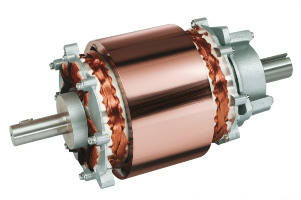
B. Wound Rotor
This is the star of the show. Unlike the simple, rugged aluminum or copper bars of a squirrel cage rotor, the wound rotor is a much more complex assembly. It’s also made of a laminated steel core but it has slots containing insulated copper windings, just like the stator. These windings are typically connected in a “star” or “Y” configuration. The crucial part is that the ends of these windings aren’t connected to each other; they’re brought out to the slip rings.
C. Slip Rings
Here’s the external connection point I mentioned. Slip rings are conductive rings (usually made of copper or a brass alloy) mounted on the motor shaft but insulated from it. There are typically three rings, one for each phase of the rotor winding. As the rotor spins, the slip rings spin with it, providing a continuous connection point for the brushes.
D. Carbon Brushes
These are blocks of conductive carbon held in a “brush gear” assembly. They are spring-loaded to maintain constant physical contact with the rotating slip rings. Their job is to transfer the current from the stationary external circuit to the spinning rotor circuit, and back again. This is the component that makes the whole system work but it’s also the main source of maintenance, as we’ll see later.
E. External Resistance/Rheostat
This is the “control box” connected to the brushes. It’s a bank of large resistors, often a liquid rheostat (where electrodes are submerged in a conductive fluid) or a grid of metal resistors. By changing the amount of resistance in this external circuit, you can directly manipulate the current flowing in the rotor. This is the secret to the motor’s incredible starting torque and speed control.
IV. Step-by-Step: How a Wound Rotor Motor Starts and Operates
Let’s walk through a typical startup sequence. Imagine we’re starting a massive rock crusher.
V. Key Performance Characteristics & Advantages
I’ve chosen wound rotor motors for projects specifically because of these benefits. When a job calls for them, nothing else will do.
A. High Starting Torque
This is the number one reason. I’ve seen these motors provide over 250% of their full-load torque on startup. A standard squirrel cage motor would either stall or draw a catastrophic amount of current trying to do the same. For something like a loaded cement mill, this is non-negotiable.
B. Adjustable Speed Control
By re-inserting some of the external resistance while the motor is running, you can increase the motor’s slip, which causes its speed to drop. This gives you a simple, robust method for variable speed control. For a crane hoist, this means an operator can lift a load quickly and then slow down for precise, gentle placement. It’s a level of control that’s hard to achieve otherwise.
C. Low Starting Current
Starting a big motor can cause a huge voltage dip on the power grid, affecting other equipment. Because the external resistance limits the rotor current at startup, the wound rotor motor draws a fraction of the starting current of a direct-on-line squirrel cage motor. I’ve measured it myself—often just 1.5 to 2.5 times the full load current, compared to 6 to 8 times for a squirrel cage.
D. Smooth Acceleration and Deceleration
By controlling how quickly the resistance is cut out, you can achieve very smooth, controlled acceleration. This reduces mechanical shock on gearboxes, couplings, and the load itself. It’s a much gentler way to get a heavy process moving.
E. Potential for Regenerative Braking
In some advanced setups, the energy from the rotor can be recovered and fed back to the power system, a process called slip energy recovery. This can improve efficiency, especially in applications where the motor frequently operates at reduced speeds.
VI. Disadvantages and Considerations
Of course, it’s not all perfect. I’ve also had to deal with the downsides, and you need to be aware of them.
- Higher Initial Cost and System Complexity: The motor itself is more expensive to manufacture due to the complex wound rotor and slip ring assembly. The external rheostat and control panel add to the overall system cost.
- Increased Maintenance Requirements: This is the big one. The carbon brushes wear down and need regular inspection and replacement. The slip rings can become dirty or grooved over time and require cleaning or even machining. A common motor problem is poor brush contact leading to performance issues.
- Potential for Reduced Efficiency: When you control speed using resistance, all that energy is dissipated as heat in the rheostat. It’s like driving your car with one foot on the gas and one on the brake. It works, but it’s incredibly inefficient.
- Larger Physical Footprint: The motor plus its external control gear takes up more space than a simple motor and starter.
- Carbon Dust Generation: The wearing brushes create conductive carbon dust, which can be an issue in clean environments or can cause short circuits if not managed properly.
VII. Common Applications Where Wound Rotor Motors Excel
So, where have I seen these motors in action? They pop up in the most heavy-duty places.
- Cranes, Hoists, and Elevators: Perfect for lifting heavy loads with precise speed control. An industry report I once read noted that over 70% of new large overhead cranes still use them.
- Ball Mills, Cement Mills, and Crushers: These machines have enormous inertia and are often started under full load. The high starting torque is essential.
- Large Conveyor Systems: Getting a long, heavy conveyor belt moving requires a gentle but powerful start to avoid snapping the belt.
- Extruders and Mixers in Process Industries: These applications often need variable speed and high torque to handle different materials.
- High-Inertia Fan and Pump Drives: For very large fans or pumps, the soft-start capability is crucial to protect the system from mechanical and electrical stress.
VIII. Wound Rotor vs. Squirrel Cage: A Comparative Overview
The choice between the two really comes down to the application’s needs. I’ve often had to make this call.
| Feature | Wound Rotor Motor | Squirrel Cage Motor |
|---|---|---|
| Rotor Design | Complex, with insulated copper windings connected to slip rings. | Simple, rugged, with cast aluminum or copper bars shorted by end rings. |
| Starting Torque | Very high and adjustable (150-300% FLT). | Moderate and fixed (100-150% FLT for standard designs). |
| Starting Current | Low and controllable (1.5-4x FLC). | Very high (5-8x FLC) unless a VFD or soft starter is used. |
| Speed Control | Simple, inherent speed control via external resistance. | Requires a Variable Frequency Drive (VFD) for speed control. |
| Maintenance | Higher. Requires regular brush and slip ring maintenance. | Very low. The rotor is virtually maintenance-free. |
| Cost | Higher initial cost for the motor and control system. | Lower initial cost. |
| Ideal Use Cases | High-inertia loads, applications needing high starting torque and simple speed control. | General-purpose applications where starting demands are moderate. |
It’s important to note that the rise of affordable and reliable VFDs has changed the game. A modern VFD can make a standard squirrel cage motor perform a lot like a wound rotor motor, offering high starting torque and excellent speed control. This is why you see fewer new wound rotor installations today. However, for sheer robustness and in many existing applications, they remain irreplaceable. The fundamental principles of the stator and rotor interaction are similar, but their construction and control methods create these vast differences in performance.
IX. Maintenance Essentials for Optimal Performance
If you have a wound rotor motor under your care, maintenance is your top priority. Ignoring it is asking for trouble. From my experience, here’s what you need to focus on:
X. Conclusion: The Enduring Role of Wound Rotor Motors
So, how does a wound rotor motor work? It works by giving you a direct line into the physics of the rotor circuit. By adding external resistance through a clever system of windings, slip rings, and brushes, it lets you command massive starting torque with minimal electrical fuss and offers a simple way to control speed.
While modern VFDs have taken over many of its traditional roles, the wound rotor motor is far from obsolete. In the world’s heaviest and most demanding industries—from mining to material handling—its rugged design and brute-force capability ensure it remains a vital and respected piece of engineering. It’s a testament to a design that prioritizes power and control above all else, and for certain jobs, there is still no substitute.