How to Accurately Measure RC Car Motor Specifications and Performance: A Comprehensive Guide
Every engineer reaches the same fork in the road. You need data you can trust before you pick a motor, adjust gearing, or qualify a supplier for motor cores and laminations. You also need a simple way to measure what matters. KV, turns, RPM, current, watts, temperature, and internal resistance sound straightforward. In practice they are not, unless you use the right tools and methods. This guide shows you how to measure RC car motors accurately then use those measurements to make smarter design and procurement decisions, including choices around stator and rotor laminations that drive efficiency and thermal performance.
We will keep it practical. We will connect measurements to design levers like gear ratio, ESC programming, LiPo voltage, and lamination material. You will see how to validate a motor’s specification sheet, how to diagnose issues like overheating or low power, and how to talk with a lamination supplier using the right terms. By the end you will have a repeatable bench process that any engineer on your team can follow.
In This Article
- Why Motor Measurements and Laminations Matter
- Engineering Fundamentals: KV, Turns, Core Losses, and Efficiency
- Tools You Need for Accurate Measurement
- Step-by-Step: Measuring KV, RPM, Current, Voltage, Temperature, Dimensions, and Internal Resistance
- Material Considerations for Laminations
- Manufacturing and Assembly Processes: Stamping, Laser Cutting, Bonding, and Interlocks
- Best Fit by Application: Crawlers, On-Road, 1/10 vs 1/8, and High-Frequency Cases
- Interpreting Data for Gearing, ESC, Batteries, and Compatibility
- Common Measurement Pitfalls
- Your Engineering Takeaway and Next Steps
Why Motor Measurements and Laminations Matter
The problem you face is simple to state. You want maximum performance and reliability with a bill of materials that your finance team accepts. Motors sit at the heart of that problem. In RC designs they define acceleration, top speed, runtime, and thermal headroom. In procurement they define risk since poor lamination material or a sloppy stack hurts efficiency and lifespan.
Measurement bridges design intent and real-world behavior. You measure KV to predict RPM per volt. You measure current and voltage to calculate watts. You measure temperature and internal resistance to judge health and efficiency. You measure shaft diameter, motor length, and mounting holes to ensure mechanical fit. You then translate those numbers into decisions about gearing, ESC ratings, LiPo battery choice, and lamination grade.
Laminations deserve a special callout. They sit inside the stator and rotor. They shape the magnetic circuit, set core losses, and limit your safe operating temperature. If you ignore lamination thickness, quality of insulation, and material choice you leave performance on the table. You also invite overheating and early failures.
Engineering Fundamentals: KV, Turns, Core Losses, and Efficiency
Let’s break down the key terms in plain English.
- KV rating (rpm per volt): KV tells you the no-load RPM per volt for a brushless motor. Apply 10 V to a 2200 KV motor on the bench. It will spin near 22,000 RPM with no load. High KV means speed. Low KV means torque and better gear flexibility. Higher KV draws more current at a given load.
- Turns (T) for brushed motors: Turns count the number of wire windings around the armature. Lower turns like 8.5T give higher RPM and higher current draw. Higher turns like 27T deliver smoother power and run cooler.
- RPM under no load vs under load: No-load RPM validates KV. Under-load RPM shows what the drivetrain and gear ratio allow in the real world.
- Current draw and voltage: Amps show how hard the motor works at a given load and gear ratio. Voltage from your LiPo or NiMH sets the ceiling for electrical power. You calculate electrical power as Watts = Volts × Amps. That wattage closely tracks real motor output on a dyno while you account for efficiency losses.
- Torque: You can estimate torque from power and speed. Power in watts equals torque in N·m times angular speed in rad/s. At lower KV you usually get higher torque density from the same motor geometry.
- Internal resistance (IR): Think of IR as the hidden tax inside your windings and connections. Lower IR means less I²R heat, better efficiency, and stronger punch. You measure it in milliohms per phase for brushless motors.
- Temperature: Heat is the scoreboard for total losses. A motor that runs at 60 to 80°C on the can under typical loads usually behaves well. Push past 90°C and you risk magnet demagnetization, bearing damage, and insulation failure.
- Core losses: This is where laminations enter. Two big culprits drive core loss: eddy current loss and hysteresis loss.
- Eddy currents behave like tiny whirlpools of wasted energy in the steel. Thinner, insulated laminations break up these whirlpools which reduces heat.
- Hysteresis loss comes from flipping the magnetization direction every electrical cycle. Materials with lower coercivity, which means lower resistance to demagnetization, cut this loss.
- Magnetic permeability: Picture permeability like a sponge for magnetic field lines. High permeability lets flux flow easily. Materials and stamping stress affect it. Better permeability means better torque per amp at the same dimensions.
Brushless vs brushed and sensored vs sensorless matter too. Sensored brushless setups give smooth starts and accurate timing data. Sensorless motors rely on back-EMF which can complicate low-speed measurement but they shine in simplicity and durability.
Tools You Need for Accurate Measurement
You cannot measure what you cannot see. This toolkit covers everything you need for RC motor bench testing and validation.
- Digital multimeter (DMM): Use it for voltage, resistance, and continuity. For current you either use a clamp meter on one lead or a shunt with measured voltage drop. Better DMMs also support four-wire Kelvin measurements at low ohms. That helps with motor winding and phase resistance.
- RC watt meter or power analyzer: Drop one inline between battery and ESC. You will capture live volts, amps, and watts. Some models log data for later graphing.
- Tachometer: Use a laser tach with reflective tape on the shaft or a sensor-based RPM pickup. ESC telemetry from brands like Hobbywing, Castle Creations, or Tekin can also report RPM.
- Infrared thermometer: Aim for the same spot on the can or endbell every time. Record the hottest point. A data logger with a thermocouple delivers continuous traces if you need deeper analysis.
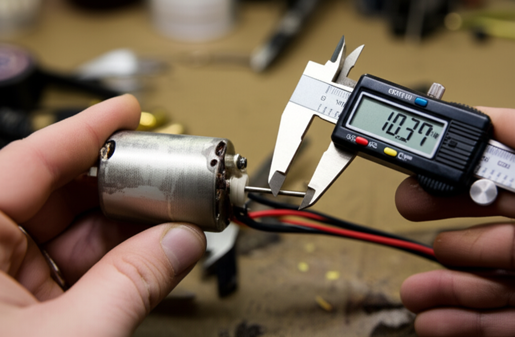
- Digital calipers and micrometer: Measure motor diameter, motor length, and shaft diameter. Check the mounting bolt pattern and motor mounting holes with calipers for a precise fit.
- Programmable ESC and programming card: You need consistent timing and throttle endpoints while you test. ESC programming for timing, startup mode, and PWM frequency changes current draw and efficiency.
- Data logger and telemetry: Systems from Spektrum or add-on loggers capture current, voltage sag, RPM, and temperature during an actual run. Real-world data beats guesses. You can also watch for thermal shutdown events.
- Bench test rig or motor dyno: A simple jig that holds the motor and allows a controlled load works for comparative testing. A proper motor dyno measures torque and computes power and efficiency under load.
- Safety: Use a stable mount. Shield the rotating shaft and pinion. Wear eye protection. High-RPM parts can fail like a small grenade.
Step-by-Step: Measuring KV, RPM, Current, Voltage, Temperature, Dimensions, and Internal Resistance
Follow this measurement sequence to build a clean data set. You can do it in under an hour for most motors. Repeat the process after break-in or after you change gear ratio.
A. Measuring KV for Brushless Motors
- Bench setup: Secure the motor firmly. Remove the pinion to prevent the drivetrain from influencing readings. Hook up the ESC and a known voltage battery. Disable timing advance and dynamic turbo modes in ESC programming. Calibrate the throttle endpoint.
- Measure no-load RPM: Use a laser tachometer on the shaft at 50% and 100% throttle. Alternatively use ESC telemetry that reports eRPM and convert to mechanical RPM with pole count. For a 4-pole rotor you divide eRPM by two. For a 6-pole rotor you divide eRPM by three.
- Capture voltage: Use a watt meter to read the battery voltage under no load at the same throttle positions. Voltage can rise a bit since current is low.
- Calculate KV: KV = RPM / Volts. Do it at multiple voltages to confirm linearity. Large deviations hint at ESC timing effects or sensorless detection limits.
- Notes: Sensorless brushless motor measurement sometimes fluctuates at very low RPM. Take measurements near mid to high duty cycle for stability.
B. Measuring RPM for Brushed and Brushless
- Test stand: Install a reflective marker. Use the tachometer while you run the motor at fixed throttle positions. Record no-load RPM, then repeat under load if you can attach a simple brake or run through the drivetrain on a stand.
- Use telemetry or a hall-based sensor: Many ESCs provide RPM estimates. You can also use a dedicated RPM sensor near the spur gear to track drive speed.
- On-load vs no-load RPM: The gap tells you about load and gearing. A large drop under load suggests aggressive gearing or high mechanical drag.
C. Measuring Current Draw
- Inline watt meter: Place it between the battery and the ESC. Record both no-load current and current under a representative load. Log burst and continuous current. Many 1/10 scale systems see 20 to 80 A continuous and 50 to 200 A bursts depending on gearing and terrain.
- Compare against ESC and battery limits: Exceeding ESC continuous ratings invites thermal shutdown. Exceeding battery C rating shortens pack life or worse.
- Phase current vs battery current: ESC logs sometimes show phase current which runs higher than battery current due to PWM and motor inductance. Know which number you are reading.
D. Measuring Voltage Under Load
- Observe sag: Use the watt meter or data logger to see voltage droop at peak current. LiPo voltage sag impacts RPM and power. A pack from Gens Ace with a higher C rating may hold voltage better which improves acceleration.
E. Measuring Motor Temperature
- IR thermometer technique: Measure at the same spot after a defined run cycle. On the bench run at fixed throttle for one minute. Then measure. In the field drive a repeatable loop then measure the can and the endbell. Try to keep peak temperature below 90°C.
- Monitor thermal shutdown: Telemetry from Castle Creations or Hobbywing ESCs often flags thermal events. Investigate gearing or cooling if you see them.
F. Measuring Physical Dimensions
- Diameter and length: Use calipers to measure OD and overall length. Common brushless 1/10 sizes are 36 mm OD with 50 to 70 mm length for 540 and 550 sizes. Larger 1/8 motors sit at 40 to 42 mm OD with longer stacks.
- Shaft diameter: Measure the output shaft. Most 1/10 motors use 3.175 mm shafts. Many 1/8 setups use 5 mm shafts. Select the pinion gear pitch and bore accordingly. Match gear pitch to your spur gear like 48P or 32P. Verify spur gear measurement and bolt pattern if you swap parts.
- Mounting pattern: Check mounting holes and the bolt pattern. Tolerances matter when you work with aluminum motor mounts that see repeated heat cycles.
G. Measuring Internal Resistance (IR)
- Four-wire method: Use a DMM that supports Kelvin probes or a dedicated low-ohm meter. Measure phase-to-phase resistance for brushless motors. Expect numbers in the single-digit milliohm to tens of milliohm range.
- ESC-based IR: Some ESCs estimate IR through a brief pulse test. Treat those numbers as relative until you verify them on a meter.
- Why it matters: Rising IR over time signals winding damage, solder joint issues, or a failing connector. It also increases I²R losses which raise motor case temperature at the same load.
Material Considerations for Laminations
Measurements tell you if a motor behaves. Laminations tell you why. The motor’s static geometry and winding design set the stage. The material choice and lamination thickness shape core losses and thermal headroom. You can think of laminations as the chassis that magnetic flux drives through.
Here are the main classes and tradeoffs you should understand.
- Silicon steels (non-oriented and oriented):
- Non-oriented electrical steel works well for motors that see flux in multiple directions. It is the default for many RC and small BLDC designs. Grades vary in core loss and permeability. See standards like ASTM A677 and IEC 60404 for typical test methods and properties.
- Oriented steels are optimized for transformers with a preferred flux direction. You almost never use them for rotating machines.
- Cobalt alloys:
- Cobalt-iron alloys offer higher saturation flux density and lower core loss at higher frequencies. They command a serious price premium. Aerospace and high power density motors use them when the performance gain justifies cost.
- Amorphous and nanocrystalline materials:
- These provide extremely low core loss at high frequency but present manufacturing challenges for rotating parts. They see more use in transformers and specialized high-frequency machines.
- Lamination thickness and insulation:
- Thinner laminations reduce eddy currents. Common thicknesses for small BLDC stators range down near 0.2 mm or less for high-frequency operation. Consistent insulation coating on each sheet is equally important since it blocks interlaminar currents. Better insulation equals lower eddy current loops which equals lower heat.
- Mechanical strength and stress:
- Stamping can introduce burrs and stress that reduce permeability. Stress-relief anneals and good die maintenance keep properties close to spec. Laser cutting avoids stamping stress for prototypes but can leave a heat affected zone if parameters are wrong.
If you want a primer that speaks to procurement and design together review the fundamentals of electrical steel laminations. It will help you translate core loss numbers into motor-level temperature and efficiency.
Manufacturing and Assembly Processes: Stamping, Laser Cutting, Bonding, and Interlocks
You have options and each one pushes on cost, tolerance, magnetic performance, and lead time.
- Stamping:
- Pros: Best for high volume. Low cost per part after tooling. Good edge quality if the die stays sharp. Predictable throughput.
- Cons: Upfront tooling cost. Possible burrs. Residual stress can reduce permeability and increase hysteresis loss unless you specify post-processing.
- Laser cutting:
- Pros: Ideal for prototypes and complex shapes. No die cost. Fast design changes. Very tight tolerance possible with proper parameters.
- Cons: Slower for high volume. Heat affected zone can raise core loss unless you tune process settings and control post-cut cleaning.
- Wire EDM:
- Pros: Excellent edge quality. Minimal thermal damage. Useful for very tight tolerances.
- Cons: Slow and expensive for volume production.
- Bonding and stacking:
- Interlocking laminations snap together like LEGO bricks. You get a rigid stack without welding that can alter magnetic properties.
- Adhesive bonding yields quiet cores with good rigidity. You avoid through-burrs but you must control cure and adhesive weight.
- Welding and riveting lock stacks firmly. Heat from welding can locally increase loss. Use them when mechanical requirements demand it then test core loss to verify the impact.
When you specify a stator core lamination for a BLDC or brushed design you define the path for magnetic flux. When you specify a rotor core lamination you define how the field interacts with the magnets and the air gap. Both decisions affect torque production, KV variation with load, and heat generation. Clean stacks with proper insulation yield better efficiency which you will see as lower current draw for the same on-load RPM.
Best Fit by Application: Crawlers, On-Road, 1/10 vs 1/8, and High-Frequency Cases
You rarely design in a vacuum. You design for a track, a tire, a voltage, a duty cycle, and a target service life.
- Crawlers and low speed, high torque:
- You often pick lower KV brushless or higher turn brushed motors. Your control loop needs smooth startup. Sensored setups help. You also benefit from laminations with lower hysteresis loss since the motor spends more time in partial load and lower electrical frequency.
- On-road and high speed:
- You push KV higher with tighter gear ratios. Core loss matters at higher electrical frequency. Thinner laminations and high-quality insulation can reduce heat build up which helps prevent thermal shutdown on long pulls.
- 1/10 scale vs 1/8 scale:
- 1/10 motors commonly sit at 36 mm diameter with 540 or 550 lengths. Shafts are usually 3.175 mm. Currents run in the 20 to 80 A continuous range depending on setup. 1/8 motors go larger at 40 to 42 mm diameters and 5 mm shafts. They draw more current and benefit from robust stacks and high saturation materials to avoid flux bottlenecks.
- Sensorless vs sensored brushless:
- Sensorless motors reduce complexity and cost. They can cog at low speed and make KV measurement trickier at minimal duty cycles. Sensored motors give smoother starts and tighter control. They also make dyno testing and telemetry validation easier.
- High-frequency PWM and timing:
- ESC timing advance increases effective KV which raises no-load RPM. It also raises current draw and heat. PWM frequency can influence acoustic noise and switching loss. Measure current and temperature before and after timing changes. Make data drive your ESC programming.
- Environmental and duty-cycle considerations:
- Sand, water, and mud increase mechanical drag which raises current draw. High ambient temperatures reduce thermal margin. Consider stronger magnets and lower core loss laminations if your use case sits near thermal limits.
For BLDC stators that must carry higher frequency flux you will often combine thin laminations with precise stacking and good insulation between layers. If you want to dig deeper into this category review the basics of a bldc stator core. You can then match stack length and tooth geometry with your slot fill and winding approach.
Interpreting Data for Gearing, ESC, Batteries, and Compatibility
You took the measurements. Now you put them to work.
- Gearing optimization:
- Use no-load RPM, KV, and battery voltage to predict top speed. Use under-load RPM drop and current draw to see if you overgeared. If case temperature climbs past 80°C on typical runs down gear or reduce timing. You can also raise spur gear tooth count or drop pinion gear size to lower load.
- Component compatibility:
- Peak current and voltage sag tell you if your ESC and battery match the task. If you logged 140 A bursts and your ESC is rated at 120 A continuous with 160 A burst you are playing with fire. Move to a higher rated ESC. Check battery C rating and actual pack voltage sag under load to verify it can deliver the amps you measured.
- Performance troubleshooting:
- High temperature with normal current usually flags poor cooling or high core loss. High current with low RPM often points to aggressive gearing or a mechanical bind. Rising internal resistance indicates electrical issues in windings or solder joints. Watch for abnormal vibration that could signal bearing issues or rotor imbalance.
- Verifying manufacturer specs:
- Compare your measured KV against the label. Do it at multiple voltages to see if it tracks linearly. Confirm shaft diameter and motor length before ordering new pinions or mounting plates. Cross-check the specification sheet for maximum voltage and current limits then confirm your test data stays inside those boundaries.
- Efficiency checks:
- Use watts in and a dyno or load-cell to estimate watts out. Efficiency equals output power divided by input power. Record temperature rise for the same load after you change timing or gear ratio. Lower temperature for the same output tells you you improved efficiency.
- Data logging and visualization:
- Export data from your watt meter or ESC. Plot RPM, volts, and amps. Look for dips and spikes. Smooth curves with modest sag tell a better story than ragged peaks. Use this to build a test report your team can repeat.
Common Measurement Pitfalls
You can ruin a test with one small mistake. Avoid these common traps.
- Measuring KV with timing enabled:
- ESC timing and turbo inflate no-load RPM. Disable them for KV checks or record both values clearly.
- Using uncalibrated or slow tools:
- A cheap tach can float several percent. A slow watt meter can miss burst currents. Calibrate where you can. Cross check with a second instrument if a number looks odd.
- Ignoring load conditions:
- No-load tests help with baselines. They do not predict thermal behavior under real load. Always run a controlled on-load test before you sign off.
- Poor temperature measurement technique:
- Different spots on the can can differ by 10°C or more. Pick a consistent spot and method. Consider a thermocouple under a zip tie on the can for better repeatability.
- Skipping mechanical dimensions:
- A mismatch in shaft diameter or motor bolt pattern can halt a build. Measure and record diameter, length, shaft size, mounting holes, and bolt pattern. Verify gear pitch and pinion bore.
- Overlooking lamination quality:
- Two motors with the same KV and geometry can run at different temperatures because one uses better laminations or cleaner stacking. If a motor runs hot at the same load check for core loss differences and IR. Engage your supplier about material grade and stacking processes.
Where Laminations Meet Measured Performance
Let’s tie it together with a clear mental model. Imagine eddy currents like small whirlpools inside the stator. Thick plates let the whirlpools grow which wastes energy as heat. Thin, insulated laminations break those whirlpools into tiny swirls which lose little energy. Hysteresis loss behaves like friction in the magnetization process. Materials with lower coercivity reduce that friction.
On the bench you feel this as:
- Lower no-load current for the same RPM when core loss drops.
- Lower case temperature under the same load and gear ratio.
- Reduced voltage sag because the battery does not need to feed as much wasted heat.
If you change from a generic steel to a high-grade silicon steel stack you often see a measurable temperature drop at the same power level. If you tighten stacking pressure and use high quality bonding you see reduced vibration and noise which improves bearing life. These trends complement the electrical checks like IR and on-load current.
For an overview of typical stacks and how they ship into motor production lines see motor core laminations. Use that language during supplier conversations so you get comparable quotes and consistent QA metrics.
Practical Reference Ranges and What They Mean
For quick planning sanity checks use these typical ranges. Always verify with your own tests.
- KV rating:
- Crawlers and torque-biased builds: 1000 to 2000 KV at 2S to 3S.
- On-road and speed runs: 3000 to 6000 KV depending on voltage and gearing.
- Turns for brushed motors:
- Low turns like 8.5T to 13.5T run hotter and faster. High turns like 21.5T to 27T run cooler with smoother control.
- No-load RPM:
- 10,000 RPM for low KV setups up to 60,000 RPM plus for high KV and high voltage. Be careful above 50,000 RPM with mechanical balancing and bearings.
- Current draw:
- Continuous 20 to 80 A in many 1/10 builds. Bursts 50 to 200 A or more in high grip runs. 1/8 platforms run higher.
- Operating voltage:
- 2S LiPo at 7.4 V up to 6S LiPo at 22.2 V for big platforms. Match motor and ESC voltage ratings. Do not flirt with margins.
- Power:
- 500 W for modest 1/10 builds up to 2500 W plus for large 1/8 or drag applications. Power scales with current and voltage so keep an eye on pack health.
- Temperature:
- Target 60 to 80°C on the can. Treat 90°C as a hard ceiling unless the manufacturer certifies higher.
- Physical dimensions:
- 36 mm OD motors dominate 1/10. 40 to 42 mm OD motors dominate 1/8. Shafts at 3.175 mm and 5 mm respectively are common.
- Internal resistance:
- 5 to 50 milliohms per phase for small brushless motors. Lower is generally better but compare apples to apples since geometry changes this number.
Build a Repeatable Test Plan
Here is a simple process you can put into a lab SOP.
1) Visual inspection and baseline:
- Record model numbers and any manufacturer labels. Note KV or turns. Check bearings for play and noise. Verify motor mounting holes and the bolt pattern.
2) Electrical baseline:
- Measure phase-to-phase IR with a Kelvin method. Check solder joints and connectors.
3) No-load tests:
- Disable ESC timing. Measure voltage, current, and RPM at 50% and 100% duty cycle. Compute KV. Log ambient temperature.
4) On-load tests:
- Pick a standard pinion and spur gear. Calibrate the tach sensor for the spur gear if you use gear-based RPM sensing. Run a timed pull on a dyno or a repeatable on-track run. Capture volts, amps, RPM, and case temperature. Note gear pitch and calculate gear ratio.
5) Thermal characterization:
- Repeat the on-load test until the motor hits thermal steady state. Record time to temperature and peak temperature. Note any thermal shutdown.
6) ESC programming sweeps:
- Adjust timing in defined steps. Repeat no-load and on-load tests. Summarize the change in current, RPM, and temperature.
7) Reporting:
- Plot current vs RPM. Plot temperature over time. Include a table for KV, IR, and shaft diameter. Provide recommendations for gear ratio adjustments.
Supplier Conversations and QA for Laminations
When you move from testing motors to qualifying suppliers focus on the lamination levers you can control.
- Material certification:
- Request certificates showing grade, thickness, and insulation type. Ask for core loss at defined frequency and peak flux density per IEC 60404 test conditions.
- Process controls:
- Ask about stamping die maintenance or laser cutting parameters. Ask about deburring processes and insulation inspection. Request sample stacks with measured stack factor.
- Stack assembly:
- Define whether you need interlocked, bonded, riveted, or welded stacks. Ask for evidence of minimal burr projections that could cause interlaminar shorts.
- Sample measurement:
- Measure a sample stator stack for OD, stack length, and slot geometry with calipers and a CMM if available. Validate electrical performance by building a sample motor and repeating the bench tests you use for incoming QC.
- Cost and lead time:
- Match the process to the volume. Laser cut for prototypes and change-heavy early runs. Stamp for volume. Be honest about performance needs and budget.
Standards and Trusted References
You do not need to reinvent the wheel. You can lean on established standards and literature when you document requirements and test plans.
- IEC 60404 series for magnetic materials and test methods.
- ASTM A677 for non-oriented electrical steel.
- IEEE Transactions on Magnetics and IET Electric Power Applications for peer-reviewed insights on core losses and BLDC design at small scales.
- ESC and motor vendor whitepapers from respected brands like Tekin, Castle Creations, Hobbywing, and LRP for setup and telemetry specifics.
Frequently Tied Design Questions
- How does lamination thickness affect motor efficiency?
- Thinner laminations lower eddy current loss at a given electrical frequency which reduces temperature rise and improves efficiency. You see the benefit most at higher RPM or high electrical frequency.
- What is the best material for a high-frequency application?
- High-grade non-oriented silicon steel often gives a good balance of cost and performance. Cobalt iron alloys deliver better saturation and lower loss at high frequency but at higher cost. Prototype and measure. Let the thermal data guide you.
- How do I verify motor specs?
- Measure KV, IR, and no-load current on your bench. Compare under-load current and temperature to the data sheet. Use telemetry or a watt meter during real runs to validate.
- How do I select gear ratio?
- Start with an estimated top speed from KV and voltage. Choose a pinion and spur that target your track’s straight speed. Log current and temperature during practice. Adjust gear ratio until you hit performance goals without crossing temperature limits.
Your Engineering Takeaway and Next Steps
Here is the bottom line.
- Measure KV, current, voltage, and RPM on a controlled bench. Then validate on-load behavior and temperature in the field.
- Keep motor case temperature below 90°C. Aim for 60 to 80°C during typical runs.
- Use a watt meter and telemetry to capture real current draw and voltage sag. Size ESC and battery to the measured peaks with realistic margins.
- Record physical dimensions early. Confirm shaft diameter, motor diameter, motor length, mounting holes, and bolt pattern before you order hardware.
- Track internal resistance as a health indicator. Rising IR warns you about looming failures.
- Choose lamination materials and processes based on application frequency, volume, and cost. Thinner insulated laminations and clean stacks reduce core loss and heat.
- Prototype with laser cut stacks if you need rapid changes. Move to stamping for cost at volume. Use bonding or interlocks to build stiff, low-noise cores.
If you are updating a platform or designing from scratch consider a quick consult with a lamination specialist. You can sync on grade, thickness, insulation, and stacking methods in one call. That conversation plus the bench measurements above will save weeks of iteration and keep your ESC logs free of thermal alarms.
Resources to continue:
- Learn how stator design choices influence torque, efficiency, and heat with this overview of stator core lamination.
- Review rotor stack options that affect magnet interaction and mechanical integration in rotor core lamination.
- If you want a material-centric view start with the fundamentals of electrical steel laminations.
- For BLDC-specific stack considerations see a focused guide on bldc stator core.
Final tip. Build a simple internal test report template. Include RC motor specs explained in one section. Add a dedicated page for brushless motor KV rating, brushed motor turns measurement, and motor Kv vs Turns comparisons. Drop in plots of on-load vs no-load RPM, amps draw, watts output, and motor case temperature from your data logger. Store the gear ratio calculation, pinion gear size measurement, spur gear measurement, and gear pitch notes near the top. Add an appendix with multimeter for RC motors techniques, tachometer RC motor methods, IR measurement RC motor steps, and ESC programming RC motor settings. Your future self will thank you when you pick up the next project and you need to compare RC motor dyno testing results, RC motor efficiency testing, and RC motor internal resistance trends at a glance.
You now have a clear path. Measure what matters. Choose materials and processes that fit your application. Use the data to guide gearing, ESC, and battery choices. Design with confidence.
Notes on typical ranges and practices in this guide derive from common RC engineering experience and from established standards like IEC 60404 and ASTM A677. For deeper theory you can consult IEEE Transactions on Magnetics or vendor application notes from major ESC and motor makers.