How to Check an Electric Motor: A Practical Troubleshooting and Lamination-Focused Guide
Every engineer reaches this moment. The motor will not start. It runs hot. It hums, trips the breaker, or vibrates like a washing machine on spin. You need a fast, reliable way to diagnose it. You also want to understand how the core design and motor laminations affect the behavior you see in the field. If that sounds familiar, you are in the right place.
This guide walks you through how to check an electric motor safely and effectively with the tools you already own. It also explains, in plain language, how lamination materials, thickness, and manufacturing choices influence efficiency, temperature rise, noise, and failure modes. You will get practical steps, clear interpretation, and design-level guidance that helps engineers, product designers, and procurement teams make smart decisions.
Before we start, a quick framing that keeps you anchored:
- Problem: You need to diagnose motor faults quickly and decide whether to repair, replace, or redesign.
- Explain: We break down tests, what readings mean, and why the motor core and lamination stack matter more than many think.
- Guide: You will see balanced trade-offs in materials and manufacturing processes.
- Empower: You will leave with steps you can act on today, and questions to bring to your lamination supplier.
In This Article
- Why and When to Inspect Your Electric Motor
- Safety First: Lockout/Tagout and Hazard Controls
- Visual and Auditory Checks: Fast Wins You Should Never Skip
- Basic Electrical Tests with a Multimeter
- Advanced Electrical Tests and Power Quality Checks
- Mechanical Checks: Bearings, Alignment, and Vibration
- What’s Really Going On: Laminations and Core Losses
- Your Options Explained: Lamination Materials and Trade-offs
- Manufacturing and Assembly Processes That Affect Motor Health
- Which Application Is This For: Matching Choices to Your Motor
- Interpreting Findings and Next Steps
- Preventive Maintenance That Works
- Industry Data and a Real-World Case
- Your Engineering Takeaway
Why and When to Inspect Your Electric Motor
Electric motors power HVAC systems, pumps, conveyors, compressors, and fans. They run 24/7 in plants and they live inside the tools and appliances in your home. When problems hit, you get downtime and costs stack up fast. That is why a simple inspection routine saves real money.
Common triggers for checks:
- Troubleshooting a motor that will not start, runs hot, or trips a breaker.
- Preventive maintenance during a scheduled outage.
- Pre-installation bench testing for a new or repaired unit.
- After a process change that increased load or changed speed with a VFD.
- Post-failure analysis to prevent repeat events.
An effective inspection blends visual and auditory clues with electrical and mechanical tests. You will also confirm nameplate data, wiring diagrams, and the motor’s environment. Then you will connect your findings to common fault types: winding issues, poor insulation resistance, bad bearings, voltage unbalance, or mechanical drag.
Safety First: Lockout/Tagout and Hazard Controls
Safety rules are not optional. Motors store energy. They live inside control circuits. Their capacitors hold charge after power is removed.
Do this before you touch anything:
- Lockout/Tagout (LOTO): Apply your company’s LOTO procedure. Lock and tag the supply isolator. Keep the key.
- Verify de-energization: Test for absence of voltage at the motor terminals with a properly rated digital multimeter (DMM). Test your meter on a known live source before and after.
- Discharge capacitors: For single-phase motors, discharge start and run capacitors with a resistor and insulated leads. Never short them with a screwdriver.
- Wear PPE: Gloves, eye protection, and arc-flash gear as required by your risk assessment.
- Respect residual energy: The rotor can spin down slowly. Springs and couplings can hold tension. VFD DC bus capacitors store energy after power down.
If your setup includes a motor starter, overload relay, contactor, fuses, or a variable frequency drive (VFD), inspect those too. Faults in the motor control panel can masquerade as motor problems.
Visual and Auditory Checks: Fast Wins You Should Never Skip
Start with your senses. Many problems jump out if you look and listen.
External examination:
- Casing and enclosure: Look for cracks, dents, corrosion, or blocked vents. Check the IP/NEMA enclosure rating against the environment.
- Wiring and connections: Loose lugs, frayed insulation, scorched terminals, wrong wire gauge, or water ingress in the conduit and junction box.
- Terminal box: Tightness, cleanliness, and correct motor connection diagram. Verify proper grounding.
- Fan and cooling fins: Broken blades, debris, and airflow restrictions. A clogged fan means heat and reduced insulation life.
- Shaft and coupling: Check for proper alignment, missing keys, rubbing, or excessive play. Use a straightedge or dial indicator if needed.
- Signs of overheating: Discolored paint on the frame, melted plastic, or that tell-tale burnt smell.
- Leaks: Oil or grease around bearing housings or seals.
Listening and feeling (with the motor running if safe):
- Abnormal noises: Grinding or growling points to bearings. Squealing can hint at belt tension or rubbing. Clicking or rattling might be loose parts.
- Excessive vibration: Misalignment, imbalance, looseness, or electrical issues. If you have a vibration analyzer, log a baseline now.
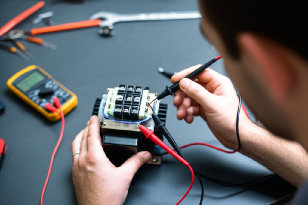
Basic Electrical Tests with a Multimeter
With power off and LOTO in place, a DMM gives you quick answers.
Winding resistance test (Ohms):
- Purpose: Detect open circuits, shorted turns, or imbalances.
- Procedure:
- For three-phase motors, measure phase-to-phase resistances: RAB, RBC, RCA at the terminal block.
- For single-phase motors, check between labeled leads per the wiring diagram.
- Measure each lead to the frame to check for phase-to-ground shorts with the ohmmeter, though this is less sensitive than a megohmmeter.
- Interpretation:
- Readings should be similar phase-to-phase. A noticeable imbalance can indicate a winding or connection problem.
- A reading near zero suggests a short. Infinite suggests an open circuit.
Continuity test:
- Purpose: Confirm conductors and internal thermal protectors are intact.
- Procedure: Use the continuity function across leads and protective devices. Check the ground wire to the frame.
- Interpretation:
- A beep or near zero ohms means a continuous path. No beep suggests an open.
Capacitor test (for single-phase motors):
- Purpose: Verify the start or run capacitor value and condition.
- Procedure:
- Discharge the capacitor safely.
- Set your meter to capacitance and measure in microfarads (μF).
- Compare to nameplate or capacitor label.
- Interpretation:
- A value within ±5 to 10% is typical for many applications. Zero or huge deviation indicates failure.
- A shorted or swollen capacitor needs replacement.
- A failed centrifugal switch in capacitor-start motors can mimic capacitor issues.
These quick checks catch many faults before you reach for advanced gear.
Advanced Electrical Tests and Power Quality Checks
Insulation resistance test (Megohmmeter):
- Purpose: Assess insulation integrity from windings to ground. This finds moisture, contamination, or insulation degradation that a DMM cannot see.
- Procedure:
- With the motor disconnected and de-energized, connect the megohmmeter from each phase to ground.
- Apply the correct test voltage per insulation class and nameplate. Common test levels are 500 V or 1000 V DC for low-voltage motors.
- Record the resistance in megaohms.
- Interpretation:
- A common rule of thumb is at least 1 MΩ per kV of operating voltage plus 1 MΩ, though many healthy motors read much higher.
- Track the Polarization Index (PI): ratio of 10-minute to 1-minute IR readings under steady test conditions. A PI above 2 is generally good for clean, dry windings.
- Watch the Dielectric Absorption Ratio (DAR): ratio of 60-second to 30-second IR values. Low PI or DAR suggests contamination or insulation aging.
Surge and dielectric tests:
- Surge testing stresses the windings to reveal inter-turn shorts. It is typically done in a motor shop by qualified personnel.
- Dielectric strength tests evaluate insulation systems under AC or DC test voltage. Use them with caution and training.
Voltage and current under load:
- Voltage measurement:
- Purpose: Confirm correct supply voltage and unbalance.
- Procedure: Measure phase-to-phase voltage at the motor terminals with the motor running when safe.
- Interpretation: A voltage unbalance above 1 to 2% can cause a current unbalance that runs much higher. Even small unbalances drive heat and reduce motor life.
- Current draw test (Clamp meter):
- Purpose: Detect overload, mechanical drag, or electrical imbalance.
- Procedure: Measure each phase current with a clamp meter during normal operation.
- Interpretation:
- Compare to nameplate full load amps (FLA).
- If current is high across all phases, suspect overload or mechanical binding.
- If one phase is high, suspect unbalance, a poor connection, or a winding issue.
Power quality analysis:
- Harmonics and poor power factor stress motors. If you suspect harmonics from VFDs or non-linear loads, a power analyzer helps.
- Motor Current Signature Analysis (MCSA) can flag broken rotor bars, eccentric rotors, bearing defects, or alignment issues without disassembly.
Mechanical Checks: Bearings, Alignment, and Vibration
Bearings take the brunt of motor failures. Industry studies often show 40 to 50% of motor failures trace back to bearings. A few simple checks go a long way.
Bearing health:
- Manual rotation: With power isolated, rotate the shaft. It should feel smooth without grit or binding.
- End play and radial play: Check the manufacturer’s spec. Excess play points to wear.
- Lubrication: Inspect grease condition and seals. Over-greasing can be as bad as under-greasing because it increases churning losses and heat.
- Advanced: If you have a vibration analyzer, trend bearing defect frequencies and overall velocity. Trending beats guessing.
Alignment and mounting:
- Coupling alignment: Use a straightedge for rough checks or a dial indicator for precision. Misalignment increases vibration and accelerates bearing failure.
- Mounting and feet: Loose bolts or a soft foot condition distorts the frame and loads bearings.
Temperature:
- Use an infrared thermometer or thermal camera to scan the frame, bearing housings, and terminal box while running.
- Hot spots reveal overload, ventilation problems, or loose electrical connections.
What’s Really Going On: Laminations and Core Losses
Why do laminations matter to diagnostics? Because core losses show up as heat, reduced efficiency, and premature insulation failure. If you only treat symptoms and ignore the magnetic core, you can fix a motor twice.
Two main loss mechanisms dominate in the core:
- Eddy current loss: A changing magnetic field induces circulating currents in the core. Think of eddies in water around a rock. Thicker laminations allow larger eddy currents which turn into heat.
- Hysteresis loss: Magnetizing and demagnetizing the core every cycle takes energy because of the material’s B-H behavior. The material’s coercivity tells you how much push it needs to switch magnetization.
How laminations help:
- Thin, insulated laminations break up eddy current paths. They act like baffles in a river that slow those whirlpools down.
- Better electrical steel with the right silicon content reduces hysteresis loss and improves magnetic permeability.
- Surface coatings provide interlaminar insulation that blocks current between layers.
This matters during checks because:
- Overheating that is not explained by load points to core loss or poor ventilation. A thermal image that shows a hot stator yoke without high current suggests core loss or shorted laminations.
- Noise and vibration sometimes trace to rotor issues like broken bars or eccentricity which interact with the magnetic field.
- Voltage unbalance raises current which raises I²R heating in copper but it also increases iron losses under distorted flux.
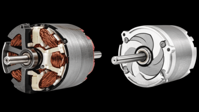
If you need a refresher on how fields interact in a motor, reviewing the motor principle and the roles of stator and rotor can be helpful for your team.
Your Options Explained: Lamination Materials and Trade-offs
Choosing the right core material makes the difference between a motor that runs cool at rated load and one that cooks itself under mild unbalance. Here is a quick guide that maps the landscape.
Material considerations:
- Non-oriented silicon steels (CRNGO, M-grades):
- Use case: General-purpose induction motors, universal motors, and many servo designs.
- Pros: Good cost-performance balance, decent loss at 50/60 Hz, stable supply.
- Watch-outs: Higher core losses than premium grades at elevated frequencies or flux densities.
- Oriented silicon steels (CRGO):
- Use case: Transformers and applications with unidirectional flux. Less common in rotating machines due to radial flux paths that change direction relative to grain orientation.
- Pros: Very low loss along the grain direction.
- Watch-outs: Not usually a fit for motors with rotating fields.
- High-silicon electrical steels and premium grades:
- Use case: Efficiency-focused motors, IE3/IE4 levels, variable speed with VFDs.
- Pros: Lower hysteresis and eddy current losses, better temperature margin.
- Watch-outs: Higher material cost, tighter handling needs to protect coatings.
- Cobalt-based alloys:
- Use case: Aerospace, very high power density, high-temperature performance.
- Pros: High saturation flux density which supports higher torque per volume.
- Watch-outs: Expensive and harder on tooling.
- Amorphous or nanocrystalline materials:
- Use case: High-frequency applications, specialty designs.
- Pros: Extremely low core loss at high frequency due to disordered structure.
- Watch-outs: Cost, brittleness, and manufacturing complexity.
You can learn more about the role and range of electrical steel laminations when you compare catalog specs against the loss and permeability your design requires.
Design levers that matter:
- Lamination thickness:
- Thinner laminations reduce eddy currents and heat. At 50/60 Hz many motors use 0.35 to 0.50 mm steel. High-efficiency or higher-frequency designs may drop to 0.20 to 0.27 mm.
- Thin material raises stamping difficulty and cost. It can also reduce stacking factor because insulation coating occupies a larger fraction.
- Coatings and insulation class:
- Organic, inorganic, or hybrid coatings increase interlaminar resistance. Protect this layer during stamping and handling.
- The motor’s winding insulation class (e.g., Class F or H) sets temperature limits for long life. Lower core loss helps you hit those limits with margin.
- Flux density:
- Running too close to saturation increases hysteresis loss and noise. It can also raise magnetizing current and heating under unbalance.
- Conservative Bmax and a clean B-H curve in your material selection cut risk.
Manufacturing and Assembly Processes That Affect Motor Health
Manufacturing choices show up in the field as heat, noise, and failures. You can design a great motor and lose it on the factory floor if processes damage the steel or the stack.
Stamping vs. laser cutting:
- Stamping:
- Best for high-volume production with tight burr control. Proper die maintenance keeps burr height low which protects interlaminar insulation.
- Heat is not the issue here. Mechanical stress and burrs are. Burrs bridge laminations and create local eddy currents that raise heat.
- Laser cutting:
- Great for prototypes, complex shapes, or low volumes. It offers exceptional precision and fast iteration.
- Heat-affected zones can degrade magnetic properties near the cut edge unless you post-process. Deburring and stress relief help.
- Waterjet and EDM:
- Niche methods for certain materials or geometries where heat input must be minimal. They can be slow.
Stacking and bonding:
- Interlocking (like LEGO bricks) creates rigid stacks without weld heat. It protects magnetic properties if done right.
- Adhesive bonding or backlack coatings produce solid stacks with good vibration damping. They add process steps but can cut noise.
- Welding and cleating are common but add local heat. Minimize length and number of welds to protect properties.
Assembly:
- Rotor balance and shaft straightness matter for vibration. A small runout difference creates a large problem at high speeds.
- Press-fit rotor bars and end rings must be defect free. Broken bars change current signature and torque ripple.
- Ensure winding insertion does not nick enamel. Nicks become partial discharges at high voltage and high dv/dt with VFD operation.
When you evaluate suppliers, look beyond price. Ask about burr height specs, coating class, stacking factor, and process controls. The quality of the motor core laminations drives efficiency and long-term reliability more than many line items on your bill of materials.
Which Application Is This For: Matching Choices to Your Motor
Three-phase induction motors:
- Most common in industry. Benefit from premium non-oriented steels with low core loss at your operating frequency.
- If you use a VFD, watch for additional iron loss from higher harmonic content. Conservative flux density and thin laminations help.
Single-phase motors:
- Capacitor-start and capacitor-run designs need healthy start components and proper centrifugal switch operation.
- Laminations still matter for temperature rise and efficiency. They also affect noise.
BLDC and PMSM:
- These motors run with permanent magnets and switching frequencies that can push iron loss up.
- Select thinner laminations and low-loss steels. Pay attention to tooth tip geometry and slotting to manage harmonics.
- For design and sourcing, review your bldc stator core options early. The lamination stack sets your torque ripple and thermal profile.
Servo and high-speed motors:
- High mechanical speeds amplify imbalance and rotor integrity issues. Rotor lamination quality and tight runout control are essential.
- Material choice shifts toward grades with low loss at higher frequencies and good saturation.
Stator vs. rotor priorities:
- Stator stacks:
- Focus on tooth tip shape, slot insulation, and thermal path to the frame.
- Insulation integrity and slot liner quality cannot slip.
- If you want to study stator stack choices, this overview of stator core lamination is a helpful starting point.
- Rotor stacks:
- For squirrel-cage rotors, bar and end ring integrity dominate. Rotor punch and stack quality drive balance and noise.
- Review your rotor core lamination requirements when torque ripple, efficiency, or acoustic limits are tight.
Transformers and special cores:
- If your project straddles motors and transformers, CRGO grades and EI or UI core styles come into play. These choices aim at unidirectional flux and low transformer loss, not rotating fields.
Interpreting Findings and Next Steps
Tie your test results together. Then map to likely faults and action.
Common patterns:
- Low insulation resistance or poor PI: Moisture or insulation degradation. Dry the motor, clean contamination, and retest. If IR does not recover, plan a rewind.
- High current on all phases with normal voltage: Mechanical overload or drag. Check bearings, alignment, and driven load.
- Current imbalance with mild voltage unbalance: Wiring or winding problem on one phase. Inspect connections, terminal block, and windings.
- Motor trips the breaker at startup: Locked rotor, bad capacitor on single-phase, seized bearings, or wrong starter settings.
- Audible grinding or high vibration: Bearing failure, misalignment, imbalance, or rotor issues.
- Hot stator frame but normal current: Core loss or shorted laminations. Investigate lamination integrity and coating damage. Consider whether the stack has been overheated in production or repaired with welding that bridged laminations.
Repair vs. replace vs. redesign:
- Repair when damage is localized, the frame and shaft are sound, and the winding can be recovered with confidence.
- Replace when multiple failure modes stack up or when energy savings from a higher-efficiency motor pay back quickly.
- Redesign when repeated failures point to a lamination or material choice that does not match the application. If the motor runs on a VFD at high switching frequency, reduce flux density and use thinner, lower-loss steel.
When to call a professional:
- Surge testing, advanced MCSA, and rewinding require expertise and equipment.
- High-voltage insulation tests above your authorization or gear rating.
- Safety-critical applications where a miss costs lives or large sums.
Preventive Maintenance That Works
A simple, disciplined plan avoids many headaches.
- Regular cleaning and inspection:
- Keep vents clear. Clean off dust and oil film that trap heat.
- Inspect terminal boxes and tighten connections on a set schedule.
- Lubrication and bearing checks:
- Follow the manufacturer’s grease schedule. Use the right lubricant and volume.
- Check for contamination or water ingress. Lubricant analysis helps with critical machines.
- Ventilation and environment:
- Confirm adequate airflow and acceptable ambient temperature. If the motor lives near corrosives or moisture, check seals and enclosure condition.
- Electrical checks:
- Quarterly insulation resistance tests on critical motors. Trend PI and DAR to catch early degradation.
- Periodic voltage and current surveys to detect unbalance and overload.
- Predictive maintenance:
- Use thermal imaging to catch hot spots in connections and bearings.
- Vibration analysis to trend bearing health and alignment.
- MCSA or current signature analysis for rotor bar issues and other faults.
Studies cited in industry guides from organizations like the U.S. Department of Energy and the Electric Power Research Institute report that predictive maintenance can reduce maintenance costs by roughly 25 to 30%, cut breakdowns by about 70 to 75%, and shrink downtime by 35 to 45%. Your results will vary with discipline and criticality.
Industry Data and a Real-World Case
Failure breakdowns from multiple studies often look like this:
- Bearings: 40 to 50% of failures.
- Stator windings: 30 to 40% due to insulation breakdown from heat, voltage stress, or contamination.
- Rotors: 5 to 10% including broken bars and eccentricity.
- Other external or electrical system issues: 5 to 10%.
Downtime cost can range from thousands to hundreds of thousands per hour in process industries. Since motors consume roughly 60 to 70% of industrial electricity, poor motor health raises energy costs fast.
Illustrative case:
- A chemical plant suffered repeat failures in a critical pump motor.
- They implemented monthly vibration analysis, quarterly MCSA, bi-annual insulation resistance testing, and regular thermal imaging.
- They caught a bearing defect and an incipient inter-turn fault early. Repairs happened during planned downtime.
- Unscheduled motor downtime fell by 80% and the plant saved more than $200,000 over the next year in avoided losses.
The lesson is simple. A few targeted predictive tools prevent emergencies and help you plan replacement cycles with confidence.
Smart Checks Tied to Lamination Health
Since this guide connects field diagnostics to lamination design, use these checks to validate core health:
- Thermal imaging after steady-state load: Compare hotspot locations to expected copper loss patterns. A uniformly hot yoke with normal current hints at core loss.
- No-load current test: If magnetizing current runs higher than expected on a healthy supply, your core may be running near saturation or suffering from increased loss due to damage.
- Audible magnetostriction “sing”: High flux density increases acoustic noise. If a repair raised stack pressure or bridged laminations, noise can change markedly.
- Elevated iron loss after a rewind: If the core got overheated or welds bridged lamination layers during rework, iron loss climbs. Shop tests can verify this before reassembly.
Nameplate, Standards, and Practical Documentation
Do not skip the paperwork. It protects you during diagnosis and procurement.
- Nameplate data: Voltage, frequency, horsepower/kW, FLA, service factor, insulation class, duty cycle, ambient rating, and temperature rise. Use these numbers during your current and voltage checks.
- NEMA and IEC frames: Check frame dimensions and mounting. The wrong frame reduces ventilation or misaligns couplings.
- Wiring diagram: Confirm connections match the supply and desired rotation. Mistakes here fuel many “motor will not start” calls.
- Insulation class vs. environment: Class F or H sets how hot you can run without cutting insulation life. Every 10°C above rating roughly halves insulation life. Lower core loss and better ventilation buy you time.
- MCC and protection settings: Overload relay curves and circuit breaker sizing must match nameplate. Too tight and you trip early. Too loose and you risk windings.
Connecting Diagnostics to Procurement Decisions
Procurement managers care about total cost. Not just purchase price. Use the data you gather to inform sourcing:
- If voltage unbalance is unavoidable, give the motor thermal margin with low-loss laminations and a conservative flux design.
- If you use a VFD, specify insulation systems compatible with high dv/dt and consider shaft grounding to cut bearing currents.
- If your application runs at partial loads for long periods, pursue lamination material that maintains low loss under your flux density pattern.
- When you solicit quotes, ask about material grade, lamination thickness, stack factor, burr height control, and bonding method. The quality of the lamination stack directly affects efficiency, temperature rise, and bearing life over the long haul.
Practical Walkthrough: Fast Troubleshooting Flow
Use this quick flow when you are onsite:
If your findings point to efficiency and heat limitations tied to core losses, involve your lamination supplier early. Getting the stack, material grade, and thickness right can solve chronic overheating that other fixes never touch.
Your Engineering Takeaway
- Start simple: Visual checks, continuity, and winding resistance catch many faults.
- Use a megohmmeter for insulation resistance. Track PI and DAR for trends.
- Measure voltage and current under load. Small voltage unbalance can cause big current unbalance.
- Bearings fail most often. Focus on alignment, lubrication, and vibration baselines.
- Thermal imaging is your friend. Hot spots highlight poor connections, overload, or core loss.
- Laminations matter. Material grade, thickness, coatings, and stacking method drive core loss and temperature rise.
- Manufacturing choices leave fingerprints in the field. Burr height, heat-affected zones, and bonding methods change magnetic behavior.
- Choose materials to match the application. Efficiency, frequency, duty cycle, and VFD use set the target.
- Document everything. Nameplate, wiring diagrams, measurements, and maintenance logs pay dividends during root-cause analysis.
If you need deeper technical background on lamination stacks and their role in performance, review your options for stator core lamination, rotor core lamination, and system-level motor core laminations with your supplier. For BLDC and PMSM designs, evaluate your bldc stator core needs early to keep torque ripple and iron loss in check. And if you are comparing material families, this overview of electrical steel laminations can help frame the trade-offs.
Ready for next steps?
- Build a standard motor inspection checklist for your plant or product line.
- Start trending IR, vibration, current, and temperature on critical assets.
- Review lamination specifications with your supplier to align material and process with your application.
- Pilot a predictive maintenance program on a small set of motors. Measure the impact on downtime and energy consumption.
You do not need mystery or magic to check an electric motor. You need a method. You need to respect the physics happening inside that laminated core. When you test with purpose and design with intention, your motors run cooler, live longer, and cost less over the full life cycle.