How to Connect a Single Phase Motor with Two Capacitors: A Step-by-Step Guide
Of course. Here is the comprehensive, long-form article based on your instructions.
Table of Contents
Introduction: Why Two Capacitors Make All the Difference
I’ve spent countless hours in my workshop and out in the field, staring down a humming, stubborn motor that just refuses to start. If you’ve ever faced this, you know the frustration. Often, the culprits are these little cylindrical components called capacitors. A single-phase motor, unlike its three-phase big brother, has a fundamental problem: it can’t start spinning on its own. It needs a little “push” to get going. That’s where capacitors come in.
Think of it like trying to push a merry-go-round. If you just push straight at the center, it won’t spin. You need to push it from the side to create rotation. A capacitor does something similar for a motor. It creates a second, out-of-sync magnetic field, essentially giving the motor that “push from the side” it needs to start turning.
But why two? Well, some motors need two different kinds of pushes. One is a massive shove to get a heavy load moving (like a compressor under pressure), and the other is a steady, efficient push to keep it running smoothly. That’s the magic of a Capacitor Start/Capacitor Run (CSCR) motor. It uses a big “start” capacitor for that initial kick and a smaller “run” capacitor for efficient, continuous operation. In my experience, understanding this dual-capacitor setup is the key to fixing and maintaining some of the most common and powerful single-phase motors you’ll find in things like well pumps, HVAC units, and heavy-duty workshop tools.
In this guide, I’m going to walk you through everything I’ve learned about wiring these motors. We’ll cover identifying the parts, making the connections safely, and troubleshooting common issues. My goal is to give you the confidence to tackle this job yourself.
Getting to Know Your Motor & Capacitors
Before you can connect anything, you’ve got to know what you’re looking at. It can seem a little intimidating at first, but once you break it down, it’s pretty straightforward.
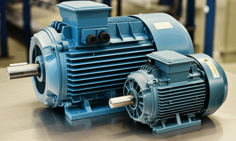
Single-Phase Motor Basics
Inside your motor, the two most important parts for our purpose are the windings. A winding is just a coil of copper wire.
- Main Winding (or Run Winding): This is the workhorse. It does the heavy lifting once the motor is up to speed.
- Auxiliary Winding (or Start Winding): This is the helper. Its job is to work with the start capacitor to get the motor spinning. It’s usually made of thinner wire and isn’t designed to be powered continuously. The relationship between the stator and rotor is what makes the motor spin, and these windings are crucial for creating the magnetic fields that drive that interaction.
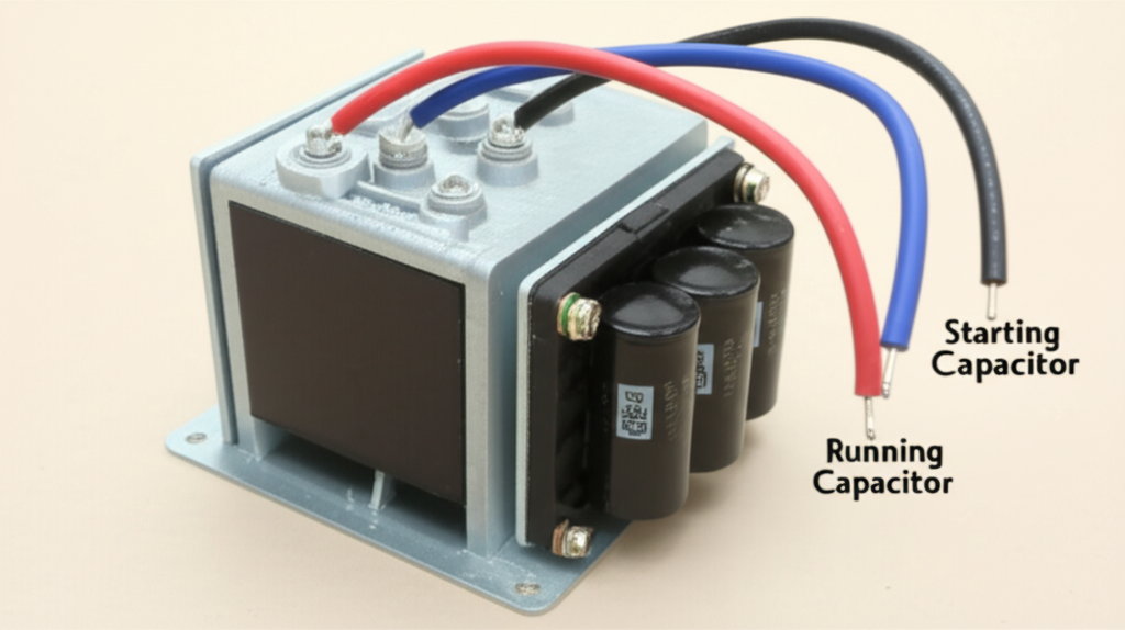
The Start Capacitor: The Sprinter
The start capacitor is built for a short, powerful burst of energy.
- Purpose: Its one and only job is to provide a massive electrical “kick” to create a high starting torque. This is what allows the motor to overcome inertia, especially when it’s connected to a heavy load like a pump or compressor.
- Characteristics: You’ll usually recognize it because it has a high microfarad (µF) rating—often 70 µF or higher. They’re typically housed in a black plastic case and are designed for intermittent duty, meaning they’re only in the circuit for a few seconds during startup before a centrifugal switch disconnects them.
The Run Capacitor: The Marathon Runner
Once the motor is spinning, the start capacitor’s job is done. Now, the run capacitor takes over.
- Purpose: The run capacitor stays in the circuit the entire time the motor is running. It smooths out the motor’s operation, improves its efficiency (what we call power factor), and reduces the amount of electricity it consumes. A motor with a healthy run capacitor runs quieter, cooler, and cheaper.
- Characteristics: These have a much lower µF rating, typically between 5 and 50 µF. They are built for continuous duty, so you’ll usually find them in a metal, oil-filled can which helps dissipate heat.
How to Tell Them Apart
When you’re looking at two capacitors side-by-side, the easiest way to tell them apart is by reading the label. Look for two key things:
Safety First: My Non-Negotiable Rules Before You Start
I can’t stress this enough: electricity is unforgiving. Before I even think about touching a wire, I follow a strict safety checklist. This isn’t optional; it’s what keeps you safe.
- Kill the Power: Find the circuit breaker or fuse that controls the motor and switch it off. Don’t just trust the on/off switch on the machine. I always go to the main panel and flip the breaker. If you can, lock it out so no one can accidentally turn it back on while you’re working.
- Discharge the Capacitors: This is a step many people forget. Capacitors store electrical energy, even after the power is off. A charged capacitor can give you a nasty shock. To discharge one, I carefully place the metal blade of an insulated screwdriver across its two terminals. You might see a small spark—that’s the stored energy being released. Do this for both the old and new capacitors.
- Wear Your PPE: Get in the habit of wearing safety glasses and insulated gloves. You never know when a wire might slip or something might short out. It’s a simple precaution that can save you a world of hurt.
- Use the Right Tools: Always use tools with insulated handles. They provide an extra layer of protection between you and any live voltage.
- Verify, Verify, Verify: My multimeter is my best friend. After I’ve shut off the power, I set my multimeter to AC voltage and test the incoming power lines where they connect to the motor. I want to see a big fat “0” on the screen. I don’t start work until I’ve confirmed there is absolutely no power present.
Gathering Your Tools and Materials
There’s nothing more frustrating than getting halfway through a job and realizing you’re missing a tool. Here’s the kit I always have ready before I start a motor wiring project.
- Multimeter: Essential for checking voltage and identifying windings. A model that can also test capacitance is a huge plus.
- Screwdrivers: You’ll need both flathead and Phillips head screwdrivers in various sizes.
- Wire Strippers/Cutters: A good pair makes clean cuts and strips insulation without damaging the copper wire.
- Pliers: I keep both needle-nose pliers for tight spots and lineman’s pliers for heavier-duty twisting and cutting.
- Replacement Capacitors: Make sure you have the right ones! Double-check that the microfarad (µF) and voltage ratings match the motor’s requirements.
- Electrical Wire: If you need to replace any wires, make sure the gauge (thickness) is appropriate for the motor’s current draw.
- Connectors: Crimp-on ring or spade terminals make for secure, reliable connections.
- Electrical Tape or Heat Shrink Tubing: For insulating your connections and keeping things tidy.
Playing Detective: Identifying Your Motor’s Terminals and Windings
Alright, this is where the real fun begins. You’ve got the motor in front of you, and it’s time to figure out what’s what.
Check the Motor Nameplate First
Your first clue is always the motor’s nameplate or a sticker on the side. In a perfect world, there will be a clear wiring diagram printed right there. It will show you exactly which terminal is which and how everything connects. This is your road map. It also tells you crucial information like the motor’s horsepower (HP), voltage, and RPM.
When There’s No Diagram: Bring Out the Multimeter
Sometimes, the diagram is missing, faded, or just plain confusing. In that case, we have to do a little electrical detective work with our multimeter. Our goal is to find three key connection points: Common, Main (Run), and Auxiliary (Start).
Here’s my process:
- Measure the resistance from Common to the other two terminals one by one.
- The terminal that gives you the lower resistance reading is the Main (Run) winding.
- The terminal that gives you the higher resistance reading is the Auxiliary (Start) winding (remember, it’s made of thinner wire, which means higher resistance).
Now you’ve successfully identified all three crucial connection points: Common, Main, and Start. You’re ready to wire it up!
The Main Event: My Step-by-Step Wiring Guide for a CSCR Motor
This is the core of the operation. I’m going to walk you through the connections one by one. I highly recommend drawing out the diagram yourself as you go. It helps solidify the connections in your mind.
For this example, let’s assume we’re connecting to a standard power supply with a Line (L1), a Neutral (N), and a Ground.
(A clear wiring diagram should be visually represented here in a real blog post)
Step 1: Connect the Main (Run) Winding
This is the simplest part of the circuit. The main winding runs whenever the motor is on.
- Connect your Common terminal directly to the Neutral (N) wire from your power supply.
- Connect your Main terminal directly to the Line (L1) wire from your power supply.
If you were to stop here and apply power (don’t do it!), the motor would just hum. It has power, but no starting mechanism.
Step 2: Integrate the Start Circuit
Now we add the “kick.” The start circuit consists of the start capacitor and the centrifugal switch, both wired in series with the start winding. The centrifugal switch is a mechanical device inside the motor that physically disconnects the start circuit once the motor gets up to about 75% of its full speed.
- Connect one terminal of the start capacitor to the motor’s Main terminal (which is also connected to L1).
- Connect the other terminal of the start capacitor to one side of the centrifugal switch.
- Connect the other side of the centrifugal switch to the motor’s Start terminal.
This series of connections—from Line (L1), through the start capacitor, through the centrifugal switch, and finally to the start winding—creates the path for that initial starting jolt.
Step 3: Integrate the Run Capacitor
The run capacitor needs to be in the circuit continuously, so we wire it differently. It goes in parallel with the start circuit, connecting the start and main windings.
- Connect one terminal of the run capacitor to the motor’s Main terminal (L1).
- Connect the other terminal of the run capacitor to the motor’s Start terminal.
You’ll notice the run capacitor effectively bridges the gap between the start winding and the main power line, staying active even after the centrifugal switch opens and disconnects the start capacitor.
Step 4: Don’t Forget the Ground!
This is a critical safety step.
- Find the green screw or bare copper wire on the motor’s frame. Connect this directly to the Ground wire from your power supply. This ensures that if there’s ever a short circuit, the electricity has a safe path to the earth instead of through you.
The Moment of Truth: Verifying Connections and Initial Motor Testing
Before you flip that breaker back on, take a deep breath and double-check everything. I like to trace each wire with my finger from start to finish, comparing it to my diagram. Make sure all connections are tight and insulated.
Once you’re confident, it’s time for a quick test.
- Stand Clear: Make sure nothing is touching the motor shaft and that you’re standing to the side, not directly in front of it.
- Brief Power-On: Flip the breaker on for just a second or two and then turn it off.
- Listen: Did it start up smoothly? You should hear a distinct “click” shortly after it starts, which is the centrifugal switch disengaging the start capacitor. You shouldn’t hear any grinding, scraping, or loud humming.
- Check Rotation: Is the shaft spinning in the correct direction for your application? (If not, you typically reverse the motor’s direction by swapping the connections on the start winding).
- Longer Test: If the initial test goes well, turn it on and let it run for about 30 seconds. Place your hand carefully on the motor casing. It will get warm, but it shouldn’t get blazing hot immediately. If it overheats quickly, shut it down.
When Things Go Wrong: Common Problems & Troubleshooting
Even with careful wiring, sometimes things don’t go as planned. Over the years, I’ve run into just about every motor problem imaginable. Here are the most common issues and how I diagnose them.
- Symptom: Motor Hums but Won’t Start.
- My First Check: The Start Capacitor. This is the number one cause. The capacitor may have failed and can no longer provide the starting kick. Test it with your multimeter’s capacitance function or just try replacing it.
- My Second Check: The Centrifugal Switch. The switch might be stuck open, meaning the start circuit never gets power. Or it could be stuck closed, which would cause the motor to overheat.
- My Third Check: Wiring. Go back and re-verify your start circuit connections. It’s easy to miswire it.
- Symptom: Motor Starts but Runs Slowly, Overheats, or Trips the Breaker.
- My First Check: The Run Capacitor. A bad run capacitor will cause the motor to run inefficiently, draw too much current, and generate excess heat. It’s the most likely culprit here.
- My Second Check: The Centrifugal Switch. If the switch is stuck closed, it’s keeping the start capacitor and start winding in the circuit. The start winding isn’t designed for continuous duty and will overheat very quickly, causing the whole motor to get hot and eventually burn out.
- My Third Check: Overload. Is the motor trying to drive a load that’s too heavy for it? A seized pump or a jammed compressor can cause these symptoms.
- Symptom: I See a Bulging or Leaking Capacitor.
- Diagnosis: It’s Dead. Don’t even bother testing it. A capacitor that is bulging, leaking oil, or has a burnt smell is toast. Replace it immediately.
Keeping It Running: Simple Maintenance Tips
Once you’ve got your motor wired correctly, you want it to last. A little preventative maintenance goes a long way.
- Visual Inspection: Every few months, just take a look at the capacitors. Check for any signs of bulging or leaking.
- Keep it Clean: Dust and debris can act like an insulator, trapping heat. Keep the motor and the area around the capacitors clean to allow for proper air circulation. Good ventilation is key to a long motor life. The quality of the internal components, like the stator core lamination, also plays a huge role in heat management and overall efficiency.
- Use Exact Replacements: When a capacitor does fail, replace it with one that has the exact same microfarad (µF) rating and an equal or higher voltage rating. Don’t guess or try to “get close.” The motor was designed for specific values.
Conclusion: Wrapping It Up for Reliable Motor Operation
Wiring a single-phase motor with two capacitors might seem complex, but as you’ve seen, it’s a logical process. By taking the time to understand the role of each component, following safety procedures religiously, and being methodical in your connections, you can confidently tackle this task.
I remember the first time I successfully brought a dead air compressor back to life by replacing and correctly wiring its capacitors. The satisfaction of hearing it roar back to life was immense. That’s the feeling I hope you get. You’re not just connecting wires; you’re taking control of your equipment, saving money, and learning a valuable skill. So take your time, double-check your work, and enjoy the confidence that comes with a job well done.