How to Connect a Three-Phase Motor: A Comprehensive Step-by-Step Guide
Table of Contents
- Introduction
- 1. Understanding Three-Phase Motor Basics
- 1.1. What is Three-Phase Power?
- 1.2. Deciphering Your Motor Nameplate
- 1.3. Motor Terminal Box Configurations
- 2. Essential Safety Precautions Before Connecting
- 2.1. Lockout/Tagout (LOTO) Procedures
- 2.2. Personal Protective Equipment (PPE)
- 2.3. Proper Grounding Requirements
- 3. Tools and Materials Required
- 3.1. Basic Electrical Tools
- 3.2. Wiring Components
- 3.3. Motor Control and Protection Devices
- 4. Common Three-Phase Motor Connection Types
- 4.1. Direct On-Line (DOL) Connection
- 4.1.1. Star (Wye) Connection
- 4.1.2. Delta Connection
- 4.2. Star-Delta (Wye-Delta) Starting
- 4.3. Connecting to a Variable Frequency Drive (VFD)
- 5. Step-by-Step Motor Connection Procedure (General)
- 6. Post-Connection Checks and Testing
- 6.1. Continuity and Insulation Resistance Tests
- 6.2. Verifying Phase Sequence and Rotation Direction
- 6.3. Monitoring Current During Start-up
- 7. Troubleshooting Common Three-Phase Motor Issues
- 7.1. Motor Not Starting
- 7.2. Incorrect Rotation
- 7.3. Overheating
- 7.4. Excessive Noise or Vibration
- 8. Compliance with Electrical Codes (NEC/IEC)
- Conclusion
Introduction
I have connected more three-phase motors than I can count. Small pump motors on farms. Big HVAC compressors in commercial towers. Conveyor drives in dusty factories. The basics never change yet every job teaches something new. If you wire a motor right it runs for years with minimal fuss. If you make one wrong assumption it lets you know fast with heat, trips, or smoke.
In this guide I will walk you through how I safely connect three-phase motors in the field. I will cover star and delta wiring, DOL starters, VFD connections, lockout/tagout, grounding, phase rotation, overload protection, and the checks I rely on before I press start. I will share practical tips, common mistakes, and simple ways to troubleshoot. I will also call out where codes like NEC or IEC shape your decisions. My goal is simple. Help you connect a three-phase motor correctly the first time.
1.1. What is Three-Phase Power?
Three-phase power uses three alternating currents that are 120 degrees apart. That phase offset delivers near constant power to the motor. Constant power means smoother torque, higher efficiency, and self-starting behavior for induction motors. That smooth torque makes three-phase motors ideal for pumps, fans, compressors, conveyors, and anything that needs reliable rotation without extra starting components. Compared to single-phase systems you get better efficiency, smaller wire sizes for the same power, and lower current per phase.
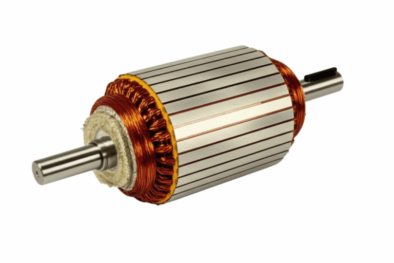
If you want a deeper background on how the magnetic fields in the stator and rotor interact the quality of the stator core lamination and the rotor core lamination matters because lamination losses show up as heat. Manufacturers cut these laminations from specialized steels which you can explore under electrical steel laminations and broader motor core laminations. Materials do not change your wiring steps yet they explain why motors run cooler and more efficiently today.
1.2. Deciphering Your Motor Nameplate
I start every installation by reading the motor nameplate. That small plate carries the facts you must match to your supply and your wiring. Here is what I look for and why it matters.
- Voltage rating and connection scheme. Many industrial motors list dual voltage and a diagram for star/wye or delta. Match supply voltage to the correct connection type.
- Current rating per voltage. This tells you expected full-load current for each voltage option. You will size wire gauge, circuit breaker, fuses, and overload relay with this data.
- Horsepower or kilowatt rating. Useful for selecting starters, VFDs, and conductors.
- RPM and frequency. 50 Hz vs 60 Hz matters for speed and torque. Pay attention when machines are imported or moved across regions.
- Service factor. Some motors allow brief overloads without damage. Do not treat service factor like free power.
- Insulation class and temperature rise. These relate to thermal limits.
- Duty cycle and ambient temperature. Critical in hot rooms or outdoors.
- Enclosure type or IP rating. TEFC, ODP, explosion-proof, and IP55 or higher in wet or dusty areas.
- Terminal markings. U1, V1, W1, U2, V2, W2 or T1 through T12 depending on standard. These labels drive your star or delta jumpers.
- Efficiency and power factor. Helpful for energy audits and power quality.
Never guess connection type. The nameplate diagram or the manual shows exactly how to bridge terminals for star or delta. I keep a picture of the nameplate with the job record so future work is easier.
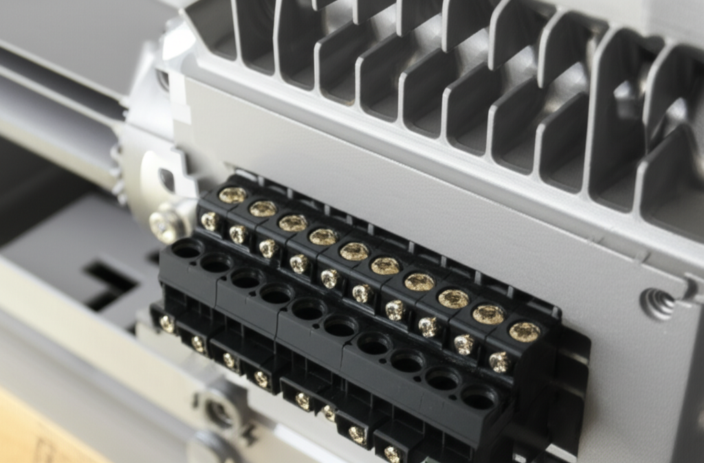
1.3. Motor Terminal Box Configurations
I often see three layouts:
- 6-wire motors. Common under IEC. Terminals often marked U1, V1, W1, U2, V2, W2. You can wire star or delta by bridging the right set of three. Supply lines L1, L2, L3 land on the remaining three.
- 9-wire motors. Typical NEMA dual-voltage motors. Leads T1 to T9. Low voltage uses delta connections with sets paralleled. High voltage uses wye connections with sets in series. The nameplate shows which leads to tie.
- 12-wire motors. Flexible for many voltages and star-delta starters. Great for larger motors or where reduced-voltage starting is planned.
Three wire vs six wire motor can confuse new techs. A three-lead motor is preconfigured internally. You cannot change connection type without opening the motor which you should not do. Six or more leads give you options for star, delta, high voltage, low voltage, and sometimes reversing within the box for special cases.
2.1. Lockout/Tagout (LOTO) Procedures
I do not touch a terminal until I have lockout/tagout in place. LOTO is not paperwork. It is your life. I isolate the circuit at the disconnect switch or breaker. I place my lock. I tag the equipment. Then I verify zero energy with a multimeter. I check line to line and line to ground. I verify that the VFD or soft starter DC bus has bled down if present. Many drives hold charge for minutes. I test my meter on a known source both before and after the check. It is a quick habit that prevents mistakes.
Industry stats reinforce this. Electrical incidents make up a small slice of workplace accidents yet they cause a high share of fatalities. BLS data lists a meaningful percentage of workplace deaths from electrical causes and a lot of those happen around industrial equipment. Do not be part of that statistic.
2.2. Personal Protective Equipment (PPE)
I wear insulated gloves and safety glasses when working in a live panel for testing. For high energy systems I use arc-flash rated clothing as required by NFPA 70E and site policy. Hearing protection helps around large MCC rooms and compressor racks. PPE is not optional when I am troubleshooting a live starter. During installation I keep the power off yet I still wear eye protection because flying wire strands hurt.
2.3. Proper Grounding Requirements
I bond the motor frame to earth ground with a proper ground wire back to the panel ground bar or the starter ground point. I check ground continuity with a multimeter. Good grounding protects people and equipment. It also helps the VFD if used because high frequency noise needs a low impedance path back to the drive. I keep the ground conductor size in line with code and breaker size.
3.1. Basic Electrical Tools
- Multimeter for voltage, continuity, and resistance
- Clamp ammeter for current during start-up
- Megger or insulation tester for winding to ground and phase to phase checks
- Wire strippers and cutters
- Screwdrivers and nut drivers
- Crimpers and lug tools
- Label maker and phase tags
- Phase sequence checker for rotation direction
3.2. Wiring Components
- Wire gauge sized to current and distance per NEC or IEC tables
- Lugs, ferrules, and terminal connectors that match wire gauge
- Conduit, cable trays, cable glands, and strain reliefs
- Heat shrink, tape, and marker sleeves
- Junction box or motor junction box extensions when space is tight
- Ground wire with proper terminations
3.3. Motor Control and Protection Devices
- Disconnect switch near the motor for servicing
- Circuit breaker or fuses sized for short-circuit protection
- Motor starter with contactor and overload relay for DOL starts
- Variable Frequency Drive for speed control or soft start
- Soft starter if you need reduced voltage starting without speed control
- Protection relays for phase loss, phase sequence, under-voltage, and ground fault
- Emergency stop circuit and push button station when the machine requires local control
- PLC or control relays for interlocks and sequencing
4.1. Direct On-Line (DOL) Connection
DOL means you apply line voltage directly to the motor through a contactor and overload relay. Simple and robust. Starting current is high which is fine for small or stiff systems.
4.1.1. Star (Wye) Connection
When do I use star. I follow the nameplate. On many six-lead IEC motors you use star for the higher labeled voltage. You tie the ends of the three windings together and feed the other ends. This increases impedance and lowers phase current at that voltage.
Typical 6-wire star wiring in the terminal box:
- Bridge U2, V2, W2 together
- Connect L1 to U1
- Connect L2 to V1
- Connect L3 to W1
- Connect ground to the ground stud
Some nameplates use T1 through T6:
- Bridge T4, T5, T6 together
- L1 to T1
- L2 to T2
- L3 to T3
I torque the screws to spec and I pull each lug to confirm it is tight. Loose jumpers cause heat and failures.
4.1.2. Delta Connection
Delta ties the end of each winding to the start of another forming a triangle. You connect line voltage to each corner. On many dual-voltage motors delta is used for the lower labeled voltage. The nameplate is the authority.
Typical 6-wire delta wiring in the terminal box:
- Bridge U1 to W2
- Bridge V1 to U2
- Bridge W1 to V2
- L1 to U1/W2 junction
- L2 to V1/U2 junction
- L3 to W1/V2 junction
With T1 to T6 notation:
- Bridge T1 to T6
- Bridge T2 to T4
- Bridge T3 to T5
- L1 to T1/T6
- L2 to T2/T4
- L3 to T3/T5
For 9-wire NEMA motors the patterns change:
- Low voltage delta. Tie T1 to T6, T2 to T4, T3 to T5. Supply L1 to T1/T6, L2 to T2/T4, L3 to T3/T5. Tie T7 to T8 to T9 together for many common motors. Always confirm with nameplate because lead groupings can vary by manufacturer.
- High voltage wye. Tie T4 to T7, T5 to T8, T6 to T9. Supply L1 to T1, L2 to T2, L3 to T3. No common tie between T7, T8, T9 in this case because they connect to T4 to T6.
I never assume a universal pattern across all brands. I read the diagram then I wire it that way.
4.2. Star-Delta (Wye-Delta) Starting
Large motors can pull 6 to 8 times full-load current on DOL start. That can drop voltage on weak systems or trip upstream protection. Star-delta starters lower starting current by first connecting the motor windings in star then switching to delta after speed builds. This needs a special starter with three contactors and an interlock timer. The motor must have six or twelve leads accessible.
I use star-delta when the process allows a short reduced torque period and the utility or plant requires a lower inrush. I size the contactors and overloads correctly because current splits differently between star and delta. The control schematic matters here so I follow the provided wiring diagram or the manufacturer’s standard.
4.3. Connecting to a Variable Frequency Drive (VFD)
VFDs changed how I approach motor starts. They provide soft start, speed control, energy savings, and protection. They also add complexity. Here is how I wire them.
- Line side. L1, L2, L3 from the supply to R, S, T on the VFD through a breaker or fuses and a disconnect. I add a line reactor or harmonic filter when specified.
- Load side. U, V, W from the VFD to the motor terminals. Keep these cables short and use shielded cable rated for VFD output to reduce EMI and reduce reflected wave effects. Terminate the shield at the drive end and bond the motor frame at the motor end.
- Ground. Bond the motor frame to ground and ground the VFD per manufacturer guidance. Good grounds cut noise and improve safety.
- Control wiring. I run start/stop, forward/reverse, speed reference, and fault reset to digital and analog inputs on the drive. I can wire a local push button station or a PLC. I keep control wiring away from VFD output cables to avoid noise.
- Programming. I set motor nameplate data in the VFD. Voltage, frequency, current, RPM, overload limit, and acceleration. I set a proper current limit and enable motor thermal protection.
Manufacturers like ABB or Siemens provide clear terminals and manuals. I follow them line by line. VFDs can save 20 to 50 percent energy on variable torque loads like pumps and fans which matches what I see in the field.
Here is the sequence I fall back on for DOL or VFD jobs. It is simple and it works.
1) Inspect motor and power supply
- Read the nameplate. Note voltage, current, connection scheme, protection class, and IP rating.
- Verify supply voltage with a meter. Confirm frequency and phase count.
- Check the motor for damage, moisture, or shipping blocks. Spin the shaft by hand.
2) Select connection type
- Choose star or delta per nameplate and available voltage.
- For dual voltage motors pick the high or low scheme as required.
- Confirm that the terminal box has the right number of leads for your plan.
3) Prepare wires
- Measure run length and select wire gauge based on current and allowable voltage drop.
- Cut, strip, and crimp lugs or ferrules. Use proper tools for a solid crimp.
4) Make internal motor connections
- Place the correct jumpers for star or delta inside the terminal box.
- Tighten with a torque screwdriver. Recheck tightness. Loose bridges are a common failure point.
5) Connect power leads
- Connect L1, L2, L3 to the correct motor terminals or to the starter output terminals T1, T2, T3.
- Keep phase order consistent with the rest of the site when possible.
- Dress wires cleanly to avoid chafe.
6) Connect ground wire
- Bond the motor frame to ground with the right size conductor.
- Confirm continuity from motor frame to panel ground bar.
7) Connect to starter or protection
- Land line power on the breaker or fuses. Then through the contactor and overload relay to the motor.
- Set the overload relay to the motor full-load current on the nameplate.
- Wire the control circuit including emergency stop and push button station.
8) Double-check all connections
- Verify tightness. Verify bridging. Verify phasing.
- Label the leads and terminals for future service.
9) For VFD jobs
- Connect line and load as per the drive labels.
- Wire control signals and verify analog scaling.
- Program the drive with motor data.
I keep a simple checklist on paper or on my phone. I tick each step as I go. It prevents the small misses that become big problems later.
6.1. Continuity and Insulation Resistance Tests
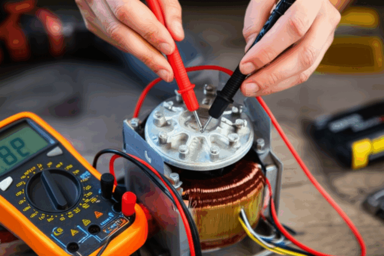
Before I energize anything I test with a multimeter and a megger.
- Continuity. I confirm that each winding has continuity and that the jumper scheme matches the expected resistance. In star I see three windings in series between any two line terminals. In delta I see the parallel path difference. I also check that there is no continuity from any winding to ground.
- Insulation resistance. I use a megger at 500 V or 1000 V depending on motor rating. I measure phase to ground and phase to phase. I look for readings in the megohm range. Lower values suggest moisture or damaged insulation. I dry the motor or stop the job if numbers look bad.
6.2. Verifying Phase Sequence and Rotation Direction
I never assume rotation. I put a phase sequence checker on L1 L2 L3 to confirm the order. Then I jog the motor for a second to see rotation direction. If it rotates wrong I swap any two phases at the motor or at the starter output. That changes the phase rotation and the motor flips direction. I always warn anyone near the driven equipment before the jog so nobody gets surprised.
6.3. Monitoring Current During Start-up
On first start I clamp each phase with a meter. I expect a short inrush then a drop toward nameplate current. If current stays high I stop and investigate. I also scan for voltage imbalance between phases. A small imbalance of just a few percent can drive big temperature rises inside the motor. I fix loose lugs, bad fuses, or supply issues before I release the motor to production.
I log motor current, voltage, and any VFD parameters at commissioning. That record helps years later when someone asks why the overload trips.
7.1. Motor Not Starting
When a motor does not start I check the simple things first.
- No power. Verify supply at the disconnect and at the starter line side.
- Control circuit fault. Check that the start command reaches the contactor coil or the VFD run input. Emergency stops and interlocks often open without a clear indicator.
- Overload relay tripped. Reset it and ask why it tripped. Do not just push and pray.
- Incorrect wiring. Verify jumpers and lead connections match the diagram. Three wire vs six wire motor confusion causes many misses.
- Single phasing. A blown fuse, loose lug, or bad contact means the motor sees two phases which is not enough to start. Protection relays for phase loss help here.
7.2. Incorrect Rotation
Rotation wrong after the first jog is normal on half the jobs. Swap any two phases at the motor or starter output and it reverses. Watch pump arrows and fan blades. Rotation errors can ruin a pump seal in seconds so do not let it run in reverse.
7.3. Overheating
If a motor runs hot I walk through this list.
- Overload. Measure current on all three phases and compare to nameplate. If the load is too high fix the mechanical issue or adjust the process.
- Incorrect connection. A motor wired delta when it should be star at the supply voltage will draw too much current. The reverse error can cripple torque. Match the nameplate.
- Voltage imbalance. Even a small imbalance drives high phase currents and heat. Fix the source which is often upstream.
- Ventilation. Check for clogged fins, blocked airflow, or high ambient temperature. Enclosed motors need clean paths for cooling.
- Harmonic distortion. VFDs can introduce heat. Use proper carrier frequency settings, output reactors, or dV/dt filters as needed.
- Insulation or winding damage. Low megger readings or thermal imaging can reveal hot spots.
7.4. Excessive Noise or Vibration
Noise points to mechanical or electrical issues.
- Loose connections. Buzzing contactors or arcing lugs can hum. Tighten them or replace worn parts.
- Bearings. Worn or dry bearings make growling or screeching sounds. Replace them and align couplings.
- Phase imbalance. The motor may shake due to uneven torque. Fix the electrical imbalance.
- Mounting and foundation. Soft foot or poor base causes resonance. Shim the feet and grout the base if needed.
- VFD settings. Low switching frequency can make an audible whine. Change the setting within manufacturer limits.
I also use vibration analysis on critical motors. It spots bearing defects early which lets you plan maintenance.
I size conductors, conduit, breakers, and overloads based on the motor current and the installation standards. In the US I follow NEC articles on motors which cover conductor sizing, short-circuit and ground-fault protection, overload protection, and disconnecting means. IEC users follow relevant standards for the same topics. I keep these points in mind.
- Circuit breaker and fuses. Choose types and sizes that provide short-circuit protection without nuisance tripping during start. Time delay fuses often work well for motors.
- Overload protection. Set the overload relay to the nameplate FLA and adjust for service factor when allowed by code and manufacturer guidance.
- Wire gauge. Use the right AWG or metric size for current and distance. Consider voltage drop on long runs.
- Conduit fill and derating. Heat matters. Follow tables for fill and ambient conditions.
- Disconnect switch. Provide a local means to lock out the motor. Label it clearly.
- Grounding and bonding. Use proper methods for equipment grounding and bonding of metallic raceways.
- Hazardous locations. Explosion proof motor wiring follows strict rules for fittings, seals, and enclosures. Use the correct IP rating or NEMA rating for the environment.
- PLC and control voltages. Segregate control wiring from power conductors. Use listed power supplies and proper fusing for control circuits.
When in doubt I ask a qualified electrician or the authority having jurisdiction. Good code compliance helps everyone who touches the system years from now.
A Practical Walkthrough: From Nameplate to Run
Let me share a real world pattern I follow for a small pump motor on a VFD. We had a 7.5 kW IEC induction motor on a water pump. Nameplate showed 400 V at 50 Hz in delta for VFD duty. The supply was 400 V three-phase.
- I isolated power and locked out the breaker. I verified zero volts at the line side of the drive.
- I opened the motor terminal box. Six leads labeled U1 V1 W1 and U2 V2 W2.
- The nameplate called for delta at 400 V with VFD. I bridged U1 to W2, V1 to U2, W1 to V2. I torqued each terminal.
- I ran a shielded four conductor cable from the VFD to the motor. Three phase conductors plus ground. I landed U V W on U1/W2, V1/U2, W1/V2 junctions respectively. I bonded ground at the frame.
- I programmed the VFD with motor voltage, FLA, RPM, and set a ramp of 5 seconds. I enabled motor thermal protection.
- I verified phase sequence at the line side then jogged the pump. It rotated correctly. Current during ramp stayed under the limit.
- We logged FLA, voltage, and drive parameters. The pump ran quiet and smooth. Energy use dropped versus the old bypass setup which matched expectations for a variable load.
That job went as planned because the basics were solid.
Pro Tips I Learned The Hard Way
- Photograph the nameplate and terminal box before and after you wire it. Future you will thank present you.
- Label each lead as you disconnect an old motor. A minute of labeling avoids an hour of guessing.
- Use proper cable glands in wet or dusty areas. Motors do not like water ingress.
- Do not mix control and VFD output cables in the same conduit. Noise will bite you.
- Verify rotation on pumps with a flexible coupling before you fully couple the shafts. It saves seals.
- Record current on each phase at commissioning. Imbalance today is failure tomorrow.
About Advanced Topics You Will Eventually Meet
- Power factor correction on three-phase motors. I add capacitor banks on large fixed speed motors to improve power factor but I do not place capacitors on the load side of VFDs.
- Phase converters and single phase to three phase converter options. Rotary and electronic converters can run small shops yet they need careful sizing and protection.
- Transformers for three-phase motors. Use them when you need a different voltage. Place them upstream of the starter or drive and follow inrush and protection rules.
- PLC motor control. Interlocks, overload trips, and start/stop commands often run through a PLC. Keep safe states in mind with E-stops and power fail conditions.
- Encoder connections. Some VFD applications use encoders for feedback. Use shielded twisted pairs and follow the drive’s grounding scheme.
Safety, Reliability, and Cost Matter
Why do I push safety and testing. Because electrical faults ruin days and sometimes lives. Studies show that a big share of motor failures are electrical which includes winding failures, insulation breakdown, and phase loss. Incorrect wiring drives those failures. Unplanned downtime can cost thousands per hour in small plants and far more in big ones. On the flip side industrial motors consume a huge slice of industrial electricity so correct connections and smart control with VFDs save real money. My experience lines up with the reported 20 to 50 percent savings on variable torque loads when you shift from DOL to VFD control.
Troubleshooting Quick Reference
- Motor not starting. Confirm power at line and load, check control circuit, reset overload, look for single phasing.
- Wrong rotation. Swap any two phases at the motor or starter output.
- Overheating. Compare current to nameplate, verify connection type and voltage, check ventilation and ambient temperature, test insulation.
- Vibration. Check bearings and alignment, confirm phase balance, secure mounting.
- Nuisance trips. Check overload settings, verify inrush and breaker curve, look for voltage drop on long runs.
FAQs I Hear On Almost Every Job
- How do I reverse a three-phase motor. Swap any two line conductors to the motor.
- Star or delta for my voltage. Follow the nameplate diagram. Do not assume a universal rule.
- Can I run a three-phase motor on single phase. You can with a phase converter or a properly sized VFD with single-phase input but you must derate the drive and follow manufacturer guidance.
- What if I only have three wires in the motor box. It is internally wired for one connection. You cannot reconfigure it without opening the motor which you should not do.
Common Mistakes You Can Avoid
- Forgetting the ground. Always bond the frame.
- Putting the wrong jumpers. Double-check star or delta bridges.
- Using the wrong wire gauge. Size per code and distance.
- Skipping the megger test. Insulation issues do not announce themselves until they fail.
- Ignoring phase sequence. A quick check prevents reverse rotation damage.
Sector Specific Notes
- HVAC motor connections often include VFDs and building automation tie-ins. Shielded cables and proper grounding make a big difference.
- Pumps and compressors care about rotation and soft starts. Use VFDs or soft starters to protect mechanical components.
- Agricultural three-phase motors deal with dust and moisture. Choose the right enclosure and keep glands tight.
- Explosion proof motor wiring in hazardous areas needs the right fittings and seals. Follow the area classification and do not cut corners.
Final Preflight Before the First Start
- LOTO in place and verified
- Star or delta jumpers match nameplate for your supply
- L1, L2, L3 landed where you expect them
- Ground is solid and continuous
- Overload relay set to FLA
- VFD programmed with motor data if used
- Phase sequence checked
- Megger and continuity tests passed
- Guards in place and people clear
If everything checks out you can start with confidence.
Conclusion
Connecting a three-phase motor is not magic. It is a method. I read the nameplate. I choose star or delta correctly. I size wire and protection per NEC or IEC. I wire cleanly and ground solidly. I test before energizing with a multimeter and a megger. I verify phase sequence and rotation. I watch current on first start. If something looks off I stop and find the cause.
Do this and your motors run cooler and longer. Your downtime drops and your energy use drops when you add VFDs to the right loads. Most of all your work stays safe. If you ever feel unsure call a qualified electrician or your local authority. It is never a bad call.
Internal links included for further reading:
- For how stator design influences efficiency see stator core lamination.
- For rotor design and induced current paths see rotor core lamination.
- For materials that reduce core losses see electrical steel laminations.
- For an overview across motor stacks and designs see motor core laminations.
Appendix: Quick Reference to Keywords and Concepts I Covered
- three phase motor wiring diagram, 3 phase motor connection types, star delta connection, delta connection wiring, star connection motor
- motor terminal box connections, connect 3 phase induction motor, how to wire a 3 phase motor
- 3 phase motor starter connection, overload protection 3 phase motor, circuit breaker for 3 phase motor
- phase rotation direction, voltage for 3 phase motor, current requirements 3 phase motor
- horsepower conversion 3 phase, motor nameplate data interpretation, electrical safety motor connection
- lockout tagout procedures, personal protective equipment (PPE), grounding a three phase motor
- VFD connection three phase motor, soft starter wiring diagram, direct on line (DOL) starter
- motor control panel wiring, industrial motor wiring, induction motor principles
- power supply for 3 phase motor, single phase to three phase converter
- troubleshooting 3 phase motor, common mistakes 3 phase wiring, professional electrician motor
- NEC codes 3 phase motor, IEC standards motor wiring
- motor insulation resistance test, phase sequence checker, motor starting current
- reduced voltage starting, wye connection diagram, three wire vs six wire motor
- motor terminal numbers, wiring diagram for specific motor HP, conduit sizing for motor wiring
- wire gauge for 3 phase motor, lugging motor terminals, motor disconnection switch
- junction box for motor, motor control schematic, protection relays for motor
- motor overheating causes, motor not starting troubleshooting, correct phase arrangement
- motor efficiency and connection, reversible 3 phase motor wiring
- dual voltage motor wiring, motor winding configurations
- power factor correction 3 phase, motor current calculation, torque speed characteristics
- PLC motor control, transformer for 3 phase motor
- surge protection motor, transient voltage protection, power quality motor effects, harmonic distortion motor
- motor grounding practices, motor lead identification, terminal strip wiring
- inspection prior to connection, post connection checks, safe start-up procedures, motor performance testing
- voltage imbalance motor, phase loss protection, motor short circuit protection
- emergency stop wiring, contactor connection motor, push button station motor
Entities and hardware I referenced
- Induction Motor, Star Connection, Delta Connection
- Variable Frequency Drive, Soft Starter, Motor Control Center
- National Electrical Code, IEC, NEMA, OSHA, NFPA
- Electrician, Electrical Engineer
- Voltmeter, Ammeter, Multimeter, Megger
- Terminal Block, Conduit, Wire Gauge, Ground Wire
- Overload Relay, Circuit Breaker, Contactor, Push Button, Motor Starter
- Squirrel Cage Motor, Disconnect Switch, Junction Box, Phase Converter
- Voltage Rating, Current Rating, Horsepower, Kilowatt, Torque, RPM
- Insulation Class, IP Rating, Fuses, Neutral Wire where applicable
- Line Conductors L1 L2 L3, Motor Terminals U1 V1 W1 U2 V2 W2 or T leads
- PLC, Transformer, Lockout/Tagout, Personal Protective Equipment
- Siemens and ABB as example manufacturers
If you follow the steps in this guide you will connect your three-phase motor safely and correctly. When in doubt slow down and check the nameplate one more time.