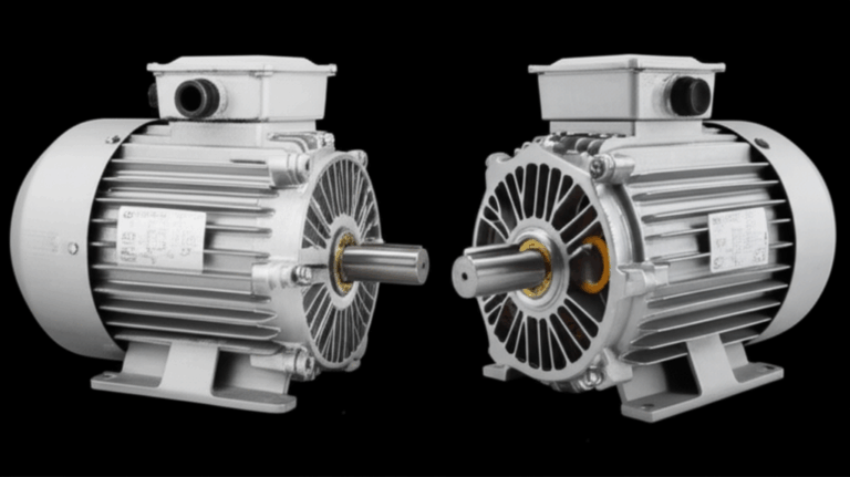
How to Meg a 3 Phase Motor: A Step-by-Step Guide to Insulation Resistance Testing
Every engineer wrestles with the same core question at some point. Is this motor electrically healthy enough to put back into service without risking a ground fault, an arc flash, or an expensive shutdown? Megging a 3 phase motor gives you a fast, decisive answer. It also helps you spot problems early, like moisture ingress or insulation degradation, so you can fix issues before they become failures.
Here’s the bigger picture that matters to design and procurement teams. Insulation resistance testing does more than prevent breakdowns. It informs maintenance schedules, supports commissioning and repair verification, and feeds predictive maintenance programs that reduce total cost of ownership. It also ties back to how the motor was built in the first place. The quality of electrical insulation, winding practices, and even the integrity of the stator and rotor core laminations influence how that motor ages, runs, and survives tough environments.
We’ll take you through the full “Problem – Explain – Guide – Empower” path. You’ll see the method, understand the physics, compare options, and walk away with a clear plan.
In This Article
- Why Megging Matters for Reliability, Safety, and Cost
- What’s Really Going On: Insulation, Core Losses, and Laminations
- Tools and Safety: What You Need Before You Test
- Step-by-Step: How to Meg a 3 Phase Motor
- Making Sense of the Numbers: Interpreting Megger Results
- Best Practices, Documentation, and Trending
- Motor Laminations 101: Materials, Manufacturing, and IR Implications
- Which Application Is This For? Matching Solutions to Your Use Case
- Your Engineering Takeaway and Next Steps
Why Megging Matters for Reliability, Safety, and Cost
Problem first. Electrical insulation breakdown sits among the top causes of motor failure. Industry studies often attribute 30–40% of failures to insulation damage. Contamination accelerates it. Moisture sinks it. Heat and voltage stress do the rest. A single unexpected motor failure can shut down a line. That can mean lost production that costs far more than the motor itself.
Insulation resistance testing protects you on three fronts:
- Safety. You uncover ground fault risks before someone gets shocked or an arc flash incident occurs.
- Reliability. You catch early signs of insulation degradation so you can clean, dry, or recondition in time.
- Cost control. Predictive maintenance that includes routine megger testing can cut unplanned downtime by 20–50% and lower maintenance costs by 5–15%.
You also create a usable history. Trending insulation resistance values lets you forecast when a motor may need service. That supports smarter procurement decisions and better asset planning.
What’s Really Going On: Insulation, Core Losses, and Laminations
Let’s unpack why this test works and why laminations still matter even though we’re measuring winding insulation to ground.
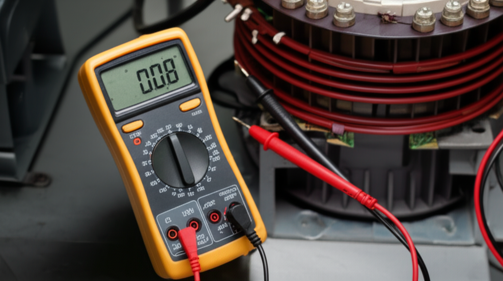
- What is megging. It’s an insulation resistance test that applies a DC test voltage from a megohmmeter (insulation tester) through a winding to the motor frame or between phases. You measure leakage current and report the result in megohms. High resistance means healthy insulation and low leakage. Low resistance means trouble.
- Think of insulation like the walls of a dam. It keeps charge where it belongs. If moisture or contamination opens tiny cracks, current leaks through. Your megger sees that leakage as a lower resistance reading.
- Polarization Index (PI) and Dielectric Absorption Ratio (DAR). These time-based tests measure how insulation “charges” with DC over time. Healthy insulation absorbs charge and its resistance rises. PI uses 10-minute divided by 1-minute readings. DAR uses 60-second divided by 30-second readings. Low ratios point to moisture or contamination.
- Core losses and laminations. The stator and rotor cores are made from stacked electrical steel laminations. Why laminations. Eddy currents are like little whirlpools in a river. A changing magnetic field stirs up these currents in solid steel. Thin, insulated laminations choke them off which cuts heat and improves efficiency. Better materials and manufacturing (thickness, grade, coating, bonding) keep losses down and temperatures lower which helps insulation last longer. High heat hastens insulation breakdown and pushes your megger values down over time.
You don’t measure lamination conductivity directly with a megohmmeter. Yet the lamination stack still affects insulation life through heat and vibration. That link matters for both design and maintenance.
Tools and Safety: What You Need Before You Test
Before you touch the motor terminal box, run a strict safety playbook. This is non-negotiable.
Required equipment:
- Megohmmeter (insulation tester). Choose a model with selectable test voltage such as 250 V, 500 V, 1000 V, and higher for HV machines. Brands like Megger, Fluke, AEMC, or Hioki are common. Verify its output and read the instrument guide before use.
- Digital Multimeter (DMM). For continuity checks, phase-to-phase resistance balance checks, and zero voltage verification.
- Personal Protective Equipment (PPE). Insulated gloves, safety glasses, arc-rated clothing per your site’s arc flash study and NFPA 70E work practices.
- Lockout/Tagout (LOTO). Locks, tags, and a documented procedure.
- Cleaning supplies. Rags, brushes, approved cleaning solvent for removing oil and conductive dust.
- Documentation. Test report or log template with fields for date, time, motor ID, location, ambient temperature, humidity, test voltage, and all readings.
Critical safety steps:
- De-energize the motor and associated circuits. Open the disconnect switch and the feeder circuit breaker. Lock and tag them.
- Verify zero energy with your multimeter at the motor terminal box and at the MCC or VFD terminals. Test for absence of voltage on all phases to ground and phase to phase.
- Discharge any capacitors if the motor has start/run capacitors or is tied to a VFD DC bus.
- Understand and mitigate arc flash hazards. Wear PPE appropriate for the task. Follow your arc flash labels and site procedures.
A quick note on environmental conditions. High humidity and condensation on a cool motor can drop insulation resistance by orders of magnitude. Record temperature and humidity. They matter when you compare results over time.
Step-by-Step: How to Meg a 3 Phase Motor
We’ll keep this crisp and practical. This procedure works for most 3 phase induction motors during commissioning, periodic maintenance, troubleshooting, or post-repair verification.
A. Pre-test inspection and preparation
- Visual inspection. Open the motor terminal box. Check for contamination, moisture ingress, oil, carbon dust, and damaged motor terminal lugs. Look at the motor terminal box connections and confirm the motor connection type. Star or delta. Confirm that links or jumpers are removed as needed for testing.
- Cleanliness. Wipe down surfaces. Remove conductive debris. Clean before you test so you don’t mistake surface leakage for real insulation breakdown.
- Motor isolation. Disconnect motor leads from power feeds and the load. If the motor connects to a VFD, isolate at both the drive output and the motor terminals to avoid charging the DC bus.
- Ground the motor frame. Confirm a solid equipment grounding conductor between frame and plant ground.
- Preliminary winding checks. Use your DMM to perform a continuity test on each winding and a phase-to-phase resistance test. The three winding resistances should be balanced within a few percent. A big imbalance points to shorted turns or an open circuit before you even reach for the megger.
B. Megohmmeter setup
- Select the correct test voltage. For most LV motors rated < 1 kV, 500 V or 1000 V DC are common. For HV motors, follow IEEE Standard 43, NEMA guidance, or the manufacturer specifications. Never exceed the recommended test voltage.
- Proper megger connection points. Connect the ground lead to the motor frame. Connect the line/test lead to the terminal under test. Keep leads clean and secure to avoid noisy readings.
C. Perform the insulation resistance tests
1) Winding-to-ground test
- Test each phase to ground separately. For example, test U1/T1 to frame, then V1/T2 to frame, then W1/T3 to frame. Make sure the other two phases are isolated during each test so parallel paths don’t skew the reading.
- Apply the test voltage for at least 1 minute unless your standard says otherwise.
- Record the insulation resistance value in megohms for each phase and note the exact test voltage.
2) Phase-to-phase test
- Test U1/T1 to V1/T2, U1/T1 to W1/T3, and V1/T2 to W1/T3. Keep the frame unconnected during these tests.
- Apply the test voltage and record readings. These values help identify breakdown between phases that won’t show up in the winding-to-ground test.
3) PI and DAR testing for advanced diagnostics
- For DAR. Perform a winding-to-ground test and record at 30 seconds and 60 seconds. DAR equals the 60-second reading divided by the 30-second reading.
- For PI. Record readings at 1 minute and 10 minutes during a constant DC test. PI equals the 10-minute reading divided by the 1-minute reading.
- Healthy, clean insulation tends to show DAR ≥ 1.25 and PI ≥ 2.0 for many machines with Class B, F, or H insulation. Low ratios point to moisture or contamination which deserve attention.
D. Special considerations
- Motors on VFDs. Inverter duty motors see steep voltage transients and high dV/dt that stress insulation. Corona resistant wire and higher insulation class help. Expect IR values to trend lower as motors age under VFD service if environmental control is poor. Megger testing helps you catch that trend before it bites.
- After moisture exposure. If the motor sat in humid conditions or was washed down, drying procedures can recover IR values. Forced warm air, space heaters, or bake-out in a controlled oven can help. Always follow the manufacturer’s limits for winding temperature.
- New motor commissioning. Always record baseline megger readings at installation. Document ambient conditions and the motor nameplate data so you can trend changes.
Making Sense of the Numbers: Interpreting Megger Results
One question comes up fast. What is a good megohm reading. The best answer looks at standards, the motor’s rated voltage, environmental conditions, and trend history.
Reference points you can trust:
- IEEE Standard 43 offers a simple rule of thumb. For many AC rotating machines rated above 1 kV, R_min in megohms equals kV of rated voltage plus 1 MΩ. For example, a 6.6 kV motor often uses a minimum of about 7 MΩ as a screen. For motors below 1 kV, practitioners often use 5 MΩ as a good value with 1 MΩ as an absolute minimum limit. Always check your manufacturer’s recommendations.
- Polarization Index criteria. PI ≥ 2.0 is often considered acceptable for many machines with modern insulation systems. Low PI points to moisture, contamination, or aged insulation.
How to read the tea leaves:
- High and stable readings across all three phases. Great. Document them and return the motor to service.
- One phase is much lower than the others. Investigate that phase. Look for localized contamination, a damaged lead, or a winding-to-frame path.
- All three are low and humidity is high. Dry the machine and retest. Temperature and humidity skew readings. Record environmental conditions with each test.
- Near zero readings to ground. You likely have a direct short to frame. Do not energize. Plan repair, rewind, or replacement.
- Fluctuating readings. Check for surface leakage across dirty terminal blocks, poor test lead connections, or intermittent faults like carbon tracking inside the terminal box.
Combine IR with other tests:
- Winding resistance balance test. Use the DMM to confirm phase-to-phase resistance balance. An imbalance suggests shorted turns or connection problems.
- Surge testing and digital diagnostics. In a motor repair shop, surge testing and advanced analytics can reveal shorted turns and weak insulation that IR alone won’t catch.
- Leakage current measurement. Some testers show microamp leakage directly. Rising leakage at the same test voltage means deteriorating insulation.
What about insulation classes. NEMA insulation class B, F, and H refer to allowable temperature rise and thermal capability. Higher temperature operation accelerates insulation degradation if materials and ventilation aren’t right. Lower core losses and good airflow keep temperatures in check.
Best Practices, Documentation, and Trending
Think of your insulation resistance program as an investment in data. The value shows up when you need to decide whether to pull a motor during a planned stop or risk running it longer.
- Document everything. Use a motor test report template. Capture date, time, test technician, motor ID, location, motor nameplate data, rated voltage, insulation class, test instrument model, test voltage, environmental conditions, winding-to-ground readings, phase-to-phase readings, and PI/DAR results.
- Temperature correction. IR changes with temperature. IEEE 43 provides correction to a standard temperature, often 40°C. Correct readings to 40°C for apples-to-apples trending. As a rough guide, IR halves for each 10°C increase in temperature for many insulation systems. Use your standard’s correction factors rather than a generic rule when accuracy matters.
- Trend over time. Look at patterns. A downward trend requires action even if today’s reading still passes a minimum.
- Frequency of testing. Test during new installation and commissioning, after motor repair or rewinding, and periodically according to your maintenance schedule. High criticality motors deserve more frequent checks.
- Common pitfalls to avoid:
- Using the wrong test voltage. Too high can overstress weak insulation. Too low can mask problems.
- Skipping LOTO. Safety first every time.
- Leaving jumpers or parallel circuits in place. You’ll get falsely high readings if you do.
- Testing immediately after washdown without drying. You’ll condemn good motors by mistake.
- Forgetting surface leakage. Clean first. Test again.
Motor Laminations 101: Materials, Manufacturing, and IR Implications
Let’s shift to a design lens because insulation resistance doesn’t live in a vacuum. The core you specify influences thermal behavior and reliability which in turn affects insulation life and the megger readings you’ll see over time.
A quick primer:
- Laminations are thin sheets of electrical steel stacked and insulated from each other to build the stator and rotor cores. Thinner laminations cut eddy current loss. Better coatings reduce interlaminar conductivity. Together they limit heat and improve efficiency.
- Hysteresis loss depends on material grade and coercivity which is the material’s resistance to being demagnetized. Low coercivity and high magnetic permeability help. Think of permeability like a sponge for magnetic flux. High permeability lets flux flow easily so the motor does more useful work with less waste heat.
- More heat equals shorter insulation life. Heat accelerates chemical changes in varnish and slot liners, dries out insulation, and reduces IR. So even though the megger test targets windings, a lower-loss lamination stack supports higher IR and longer life in the real world.
Material considerations:
- Silicon steels (M grades). The workhorse for industrial motors. Solid performance and good cost. Thinner gauges perform better at higher frequencies but increase cost.
- High-grade electrical steels for premium efficiency. Lower core losses reduce operating temperature which boosts insulation life. You balance cost and performance based on duty cycle and energy cost.
- Cobalt alloys. Exceptional magnetic performance for aerospace and high-power-density designs at high cost. Use when performance overrides cost pressure.
- For BLDC and high-frequency machines. Very thin laminations and premium coatings reduce eddy currents where switching frequencies and harmonic content run high.
Manufacturing and assembly:
- Stamping vs laser cutting. Stamping shines in high-volume production with consistent burr control and cost efficiency. Laser cutting enables rapid prototyping and complex geometries with quick turn but can increase edge losses unless carefully managed.
- Interlocking laminations vs welding. Interlocking works like LEGO bricks and avoids heat affected zones that degrade magnetic properties. Bonding and cleating are options that deliver strong stacks without welding heat.
- Coatings and insulation. Proper interlaminar insulation keeps eddy currents in check. Skimp on coating quality and you pay with elevated core loss and heat.
If you want a deeper look at how core construction ties to motor performance, these resources help:
- Explore the role and geometry of the stator core lamination
- Compare options for the rotor core lamination
- See the broader landscape of motor core laminations
- Review materials and coatings used in electrical steel laminations
How laminations affect your megger program:
- Cooler-running cores extend insulation life which keeps IR values higher for longer. That translates to longer intervals between repairs and fewer marginal readings.
- High-frequency stress from VFDs increases eddy current heating and introduces voltage transients. Inverter duty designs with premium laminations and improved winding insulation tolerate this environment better.
Which Application Is This For? Matching Solutions to Your Use Case
You have options depending on your motor’s duty, environment, and criticality. Let’s map common situations to practical choices.
- General-purpose industrial motors on across-the-line starters:
- Material. Standard silicon steel M grades with proven coatings. Focus on thermal design and cooling.
- Manufacturing. Stamping for volume. Interlocking or bonding to preserve properties.
- Insulation system. Class F or better with quality varnish and slot liners. PI ≥ 2.0 is a healthy sign during acceptance tests.
- Megging. Use 500–1000 V DC test voltage per manufacturer guidance. Document baseline values at commissioning.
- Motors on VFDs in harsh environments:
- Material. Lower-loss laminations to limit heat. Consider thinner gauges if harmonics are significant.
- Insulation. Inverter duty windings with corona resistant wire and reinforced turn insulation. Monitor IR closely and trend over time.
- Additional tests. Consider partial discharge testing for MV machines if insulation stress is severe.
- Megging. Isolate the drive before testing. Confirm DAR and PI to catch moisture and contamination early.
- High-power-density or aerospace applications:
- Material. Cobalt alloys or very high-grade electrical steel. Tight stacking factors and minimal burrs.
- Manufacturing. Precision stamping or fine laser cutting for prototypes then firm up a stamping process for production.
- Cost trade-offs. Higher material cost buys lower heat and higher efficiency which can be necessary for weight or performance targets.
- Megging. Higher test voltages for HV machines per IEEE 43 in conjunction with a rigorous QA process.
- Maintenance and repair scenarios:
- When do you clean and dry. If IR is low across all phases and the environment is humid, start with drying and cleaning. Retest before calling for a rewind.
- When do you rewind. If IR is near zero or you see clear signs of insulation breakdown and low PI, schedule a rewind. Pair it with an inspection of the lamination stack for hot spots or delamination.
- When do you replace. Compare motor repair cost vs replacement. Old cores with significant losses and recurring failures can justify new motors with improved laminations and insulation systems.
- Commissioning and periodic programs:
- Pre-commissioning checks. Confirm continuity, balanced phase resistances, correct motor connection types such as star/delta, and proper motor terminal box connections. Run winding resistance measurement and verify motor rated voltage for testing.
- Periodic testing cadence. Critical assets get quarterly or semi-annual IR tests. Non-critical assets can go annual. Use predictive analytics to watch trends and adjust intervals.
Your Engineering Takeaway and Next Steps
Here’s the short list you can use today.
- Insulation resistance testing is a fast, powerful screen. It finds moisture ingress, contamination, and insulation degradation before they become failures.
- Follow safety procedures every time. LOTO, PPE, and zero-energy verification protect your team and equipment.
- Use the right test voltage. Follow IEEE Standard 43 and the manufacturer’s guidance. For many LV motors, 500–1000 V DC works. For HV machines, use the standard’s recommended values.
- Record environmental conditions. Temperature and humidity change IR. Correct to a standard temperature for trending.
- PI and DAR strengthen your decision-making. Healthy insulation shows improving resistance over time during the test. Low ratios flag contamination or aging.
- Interpreting results is about context. Absolute numbers matter yet trends matter more. A clean motor typically shows higher values with stable or improving PI.
- Laminations influence insulation life. Lower core losses and better stack construction reduce heat which supports higher IR for longer service life.
- Pick materials and manufacturing methods that fit your application. Stamping for volume and cost efficiency. Laser cutting for complex prototypes. Interlocking or bonding over welding to preserve magnetic properties when possible.
- For VFD motors. Use inverter duty insulation. Expect harsher electrical stress. Trend IR more closely and keep an eye on operating temperatures.
Actionable next steps:
- Build a standard test report template and train technicians on a repeatable procedure.
- Establish baseline IR, DAR, and PI for each motor at commissioning.
- Trend readings in your CMMS or reliability software. Use alerts for downward trends.
- If you see marginal values. Clean, dry, and retest. Use the data to plan repairs during scheduled downtime.
- For design and procurement. Work with your lamination supplier to optimize materials and stack construction for your duty cycle. Ask for loss curves at your operating frequency and temperature. Confirm insulation class and varnish system compatibility with VFDs where applicable.
- When in doubt. Schedule a technical review with your motor manufacturer or a trusted testing service. Bring your data and environmental conditions. You’ll make faster, better decisions.
Final note on standards and sources you can trust:
- IEEE Standard 43 provides accepted guidance on insulation resistance testing, test voltages, and temperature correction.
- NEMA and IEC standards frame insulation classes and motor performance ratings.
- OSHA and NFPA 70E define safe work practices for electrical testing.
You don’t have to guess. A disciplined insulation resistance testing program combined with smart material and design choices for the lamination stack gives you safer starts, fewer surprises, and longer motor life. If you need a deeper dive on lamination selection for your application or want to sanity check your test plan, start a conversation with your engineering team and your lamination supplier. Bring your performance targets, duty profile, and budget to the table. You’ll leave with a clear path forward.