How to Mount a Trolling Motor on a Kayak — and the Motor Lamination Decisions That Make It Work
Every design engineer who touches small marine propulsion runs into the same friction. You need a trolling motor that mounts cleanly on a kayak and feels invisible to the paddler. You need quiet power. You need long battery life. You need stability and safety in spray and chop. Under all those user-visible wins sits one critical interior choice that decides efficiency and heat profile more than almost anything else. The motor core laminations.
So yes, we will walk through practical mounting methods and wiring basics. That helps the installer and it informs your design constraints. The backbone of this article will focus on the motor’s heart. The stator and rotor laminations. The electrical steel you choose. The way you cut and stack it. Those calls drive thrust per amp, acoustic signature, and thermal headroom. Which means they drive real-world kayak range and user satisfaction.
Read this as a field guide from a partner who builds and validates these parts every day. I will call out trade-offs. I will keep the physics clear. Then I will leave you with a simple checklist so your next design review runs faster.
In This Article
- Why motorize your kayak? Benefits and key design considerations
- Choosing the right trolling motor for your kayak
- Selecting the optimal mounting method
- Essential tools and materials checklist
- Step-by-step installation guide
- The engineering fundamentals: why laminations matter
- Material considerations for motor laminations
- Manufacturing and assembly processes for laminations
- Which application is this for? Matching designs to use cases
- Crucial safety considerations for motorized kayaks
- Maintenance tips for longevity
- Troubleshooting common issues
- FAQs about kayak trolling motor installation
- Engineering takeaway and next steps
Why Motorize Your Kayak? Benefits and Key Considerations
When anglers and paddlers go electric they want more hours on the water with less fatigue. They want hands-free boat control for casts. They want precise station keeping near structure. That drives motorization in fishing kayaks and even inflatable kayaks. From an engineering perspective those benefits translate to measurable design drivers.
- Enhanced fishing control and efficiency. GPS anchoring like Spot-Lock reduces drift near a submerged point or a weed edge. That requires smooth torque response at low speed and low ripple. This pushes you toward refined stator slot geometry and optimized lamination stacks.
- Increased speed and range. Users compare speed at 30 lb vs 55 lb thrust ratings. You need to deliver real thrust without a runaway current draw. Core loss and copper loss are your levers.
- Reduced fatigue. A quiet motor with low vibration is not optional. Noise ties back to electromagnetic forces which trace to tooth shape and stack symmetry. It also ties to mechanical balancing and propeller design.
- Constraints you must assess early: kayak type and hull stiffness, stability, max load, local regulations, salt vs fresh, budget. A sit-on-top kayak handles weight midship better than a narrow touring boat. An inflatable kayak needs a lighter motor and a gentle mounting approach.
A quick reality check on load. Many “fully loaded” kayak builds hit 450–650 lb once you count the kayak, angler, motor, battery, tackle, and water. That load matters for thrust selection and for heat budget inside a compact motor housing.
Choosing the Right Trolling Motor for Your Kayak
Let’s translate user-facing specs into engineering implications. These choices inform your lamination material and stack geometry too.
- Thrust rating. A common rule of thumb is 2 lb of thrust for every 100 lb of fully loaded weight. Bump to 3–5 lb per 100 lb in wind or current. A 600 lb loaded kayak will feel underpowered at 20 lb thrust. Many end up with 30–55 lb thrust motors. That thrust must come without cooking the windings or saturating the core. Good lamination selection buys you margin.
- Shaft length. Propeller depth should run about 6–12 inches below the surface in calm water. Too shallow invites ventilation. Too deep wastes energy. Shaft length also sets the moment arm into the mount which feeds your stress analysis.
- Control options. Hand tiller is simple. Foot pedal and remote control raise expectations for smooth torque steps and position holding. GPS features like Spot-Lock work best with tight speed control and a low-noise electromagnetic design.
- Water type. Saltwater motors need marine grade components. Think 316 stainless hardware and robust coatings. The lamination material sits inside a housing yet you still benefit from moisture-resistant bonding and careful insulation class selection.
- Top brands used as benchmarks. Minn Kota and MotorGuide set standard expectations for thrust envelopes and usability. Bixpy Jet shows the market pull toward lightweight modular motors for inflatable and smaller hulls.
Add battery choice to the design picture. Many anglers now carry a 50–100 Ah LiFePO4 battery because it weighs half as much as lead acid and holds voltage better under load. Lithium shifts the weight distribution which changes how the kayak trims. Put the battery mid-ship to protect primary stability.
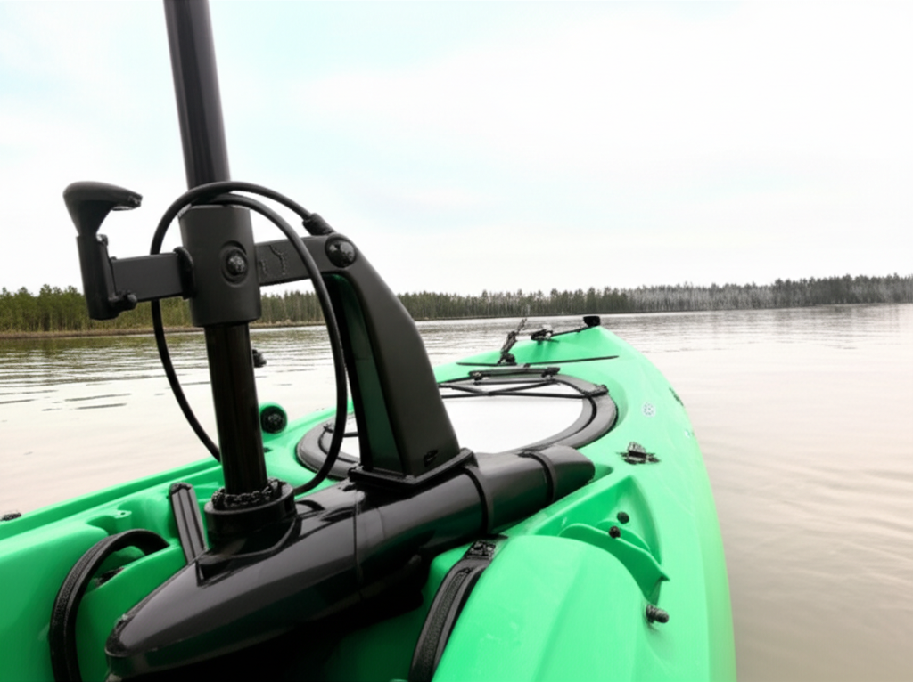
Selecting the Optimal Mounting Method
Mounting drives the user experience and feeds back into loads seen by the motor and bracket. That informs your housing design and fastener spec.
- Transom mount. Simple and direct. It delivers thrust in line with the hull. It can interfere with rudder steering on some kayaks. Installation is straightforward with a transom plate or reinforcement. A well designed DIY transom can fail if you skip a backing plate. The stress concentrates near bolt holes in unsupported plastic.
- Bow mount. Superior tracking for anglers who want to pull the boat through a drift. You gain precision and hands-free control with foot or remote input. You also add complexity and weight to the bow. A bow mounting plate needs a broad footprint and internal reinforcement.
- Side mount. Versatile and easy to deploy. It introduces asymmetric thrust and can tangle with the paddle stroke. Many use accessory rails from YakAttack, Railblaza, or StarPort. Respect the rail system’s rated load and test for flex.
- Scupper hole mount. Appealing because it avoids drilling in some designs. It can put stress on thin hull sections. It also limits the motor location which can reduce prop clearance.
- Internal mount. Certain kayaks integrate a pod or well that accepts a compact motor. It keeps the motor protected and clean. It demands a motor with tight packaging and smart cooling.
Design clue. When you size the mount reinforcement assume dynamic loads from waves and starts. It is not just static thrust. Test for repeated torsional cycles. More than a few DIY mounts fail from small backing plates or soft materials like unreinforced PVC.
Essential Tools and Materials Checklist
Whether you are validating a mounting kit or building one in-house, expect to see the following list. Your engineering team can include these in documentation to improve field outcomes.
- Motor and mount. A compatible trolling motor and a well matched mounting bracket or plate.
- Hardware. Marine grade stainless bolts, nuts, washers, and a backing plate. 316 stainless resists salt better than 304.
- Sealant. A marine polyurethane sealant like 3M 5200 for permanent seals. 3M 4200 if you may remove it later.
- Power system. Deep cycle or lithium battery, a waterproof battery box, marine grade wire, a manual reset circuit breaker or fuse sized to the motor, crimp connectors, and heat shrink.
- Tools. Drill with stepped bits, wrenches, screwdrivers, measuring tape, marker, wire strippers, and crimpers. A deburring tool protects the hull when you drill.
Engineers can help installers by adding clear torque specs for fasteners and by calling out minimum backing plate size and material. HDPE or marine plywood spreads load better than small washers.
Step-by-Step Installation Guide
This section speaks to the installer. It also flags where engineering decisions reduce risk in the field.
1. Planning and preparation
- Read the motor and mount manual. Check the hull structure. Verify balance and access.
- Mark drill points with the bracket clamped in place. Confirm prop clearance.
- Plan battery placement and cable routing. Keep heavy items near the center.
2. Drilling mounting holes
- Use sharp bits and slow speed in plastic. Step up through sizes.
- Deburr holes on both sides. Sharp edges create stress risers.
- Clean the area before sealing.
3. Securing the mounting bracket
- Apply marine sealant to holes and under the bracket. Add sealant to fastener threads.
- Install bolts with oversized washers and a solid backing plate. Tighten evenly without crushing the hull.
4. Attaching the trolling motor
- Mount the motor to the bracket and check deploy and stow functions.
- Set shaft depth so the prop sits below the surface in chop. Confirm no interference at full steering sweep.
5. Battery and electrical wiring
- Secure the battery box. Strap it down. Vent it if lead acid.
- Use the right gauge marine wire. Keep runs short. For many 12V kayak trolling motors up to 55 lb thrust use 8 AWG for total runs up to 10 ft. Step to 6 AWG for longer runs.
- Install a correctly rated circuit breaker within about 7 inches of the battery positive. A 40–60 A breaker works for most 30–55 lb thrust motors. Check the motor manual. Fuse rating should match the motor’s current draw with headroom for surge.
- Make all electrical connections waterproof. Heat shrink butt splices or solder and adhesive-lined heat shrink. Consider a waterproof wiring harness. Label everything.
6. Testing and fine-tuning
- Dry test the motor on land. Verify forward and reverse. Check steering and deploy.
- On-water test at low speed first. Adjust shaft depth for minimal cavitation and tip-in noise.
- Verify battery voltage and current draw. Log baseline data for future troubleshooting.
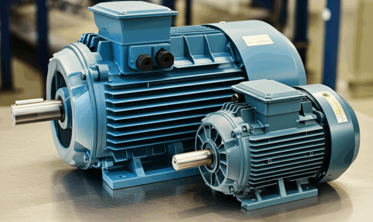
The Engineering Fundamentals: Why Laminations Matter
Now let’s open the motor. The core laminations inside your trolling motor decide how much power you waste as heat. They decide acoustic behavior and torque ripple too.
Think of eddy currents like tiny whirlpools in a river. A changing magnetic field induces a voltage in the metal core and that drives circulating currents. Those currents waste energy as heat. Thin, insulated laminations break up the whirlpools and block those circulating paths. You get lower eddy current loss and cooler operation.
Two primary core losses set your floor.
- Hysteresis loss. Energy lost as the magnetic domains flip back and forth each cycle. It scales with frequency and with the material’s hysteresis loop area. Materials with lower coercivity lose less here. Coercivity is the material’s resistance to being demagnetized.
- Eddy current loss. Energy lost due to induced currents in the core. It increases with frequency and with the square of lamination thickness. Thinner laminations reduce this loss far better than a single thick piece of steel.
Permeability also matters. Magnetic permeability is how easily the material carries magnetic field. Think of it like how a sponge soaks up water. Higher permeability up to a point means more efficient flux paths and lower magnetizing current.
This is why every efficient motor uses insulated laminations rather than a solid core. Better laminations buy you:
- Higher motor efficiency which yields longer run time at each battery charge.
- Lower internal temperatures which increases winding life and insulation reliability.
- Smoother torque and less acoustic noise when geometry and stacking are done well.
If you want a quick primer on the building blocks of these parts see this overview of motor core laminations. It shows how lamination stacks sit at the heart of small traction and trolling motors.
Standards worth knowing:
- IEC 60404 series for methods of measuring magnetic properties. Your lab should familiarize itself with the right parts of this series for core loss and permeability.
- ASTM A677 for nonoriented electrical steel sheet and strip.
- ASTM A976 for classification of electrical steel by core loss and permeability.
- ABYC E-11 for DC electrical systems on boats. This is wiring not lamination related yet it governs many harness and overcurrent protection decisions in marine applications.
Material Considerations for Motor Laminations
Kayak trolling motors operate at low voltage and modest frequency compared to high-speed BLDC spindles. They still benefit from careful electrical steel selection.
- Nonoriented silicon steels. The workhorse for general purpose motors. M-grades balance loss, permeability, and cost. Common thickness ranges for small motors are 0.50 mm down to 0.35 mm or thinner for higher frequency sections. Thinner means less eddy current loss. It also means more sheets for a given stack height which increases stamping and stacking time.
- Grain oriented electrical steels. CRGO shines in transformers and some axial flux use cases that favor a fixed flux path along the rolling direction. Most radial flux motors use nonoriented grades. Use CRGO selectively if your geometry aligns with its anisotropy. Otherwise stick with CRNGO.
- Higher silicon content grades. Silicon reduces core loss and increases resistivity. It can make steel more brittle. That affects stamping and handling. Your supplier should advise on burr control and tool wear.
- Cobalt alloys. They bring high saturation flux density and low loss at high frequency. They also bring high cost. You rarely need cobalt in a mainstream kayak trolling motor. You may consider it if you chase extreme power density and need the smallest possible pod.
- Insulation coatings. Each lamination needs a surface coating that insulates it from its neighbors. Coating class, cure, and thickness feed into punchability and interlaminar resistance. Ask for data from batch coupons not brochure values.
If you want a concise explainer on the base material families and how they roll into motor stacks, see electrical steel laminations. It covers silicon content, coatings, and application fit.
Manufacturing and Assembly Processes for Laminations
Material picks matter. Process decisions often matter more for repeatable results.
- Stamping. The standard for volume. You get low cost per part once you amortize tooling. You get fine burr control with good tool steel and maintenance. Stamping can introduce plastic deformation at the edge which raises loss if burrs remain. Tight die control and deburring keep you in spec.
- Laser cutting. Great for prototypes and low volume. You can iterate geometry and slot skew without a new die. Heat affected zones increase local loss if you do not manage cutting parameters and post processing. For a small production run that trades off cost vs speed this can be your best option.
- Waterjet. Used less often for electrical steels because it can taper edges at high speed. It avoids heat affected zones which keeps losses low. It tends to be slower and costlier than stamping in production.
- EDM. Shells out precision for small quantities. Not typical for this application.
Stacking and joining:
- Interlocking. Think LEGO bricks. Tabs and slots pull sheets into a rigid stack with no weld heat. Done well it yields a stable stack with good electrical isolation.
- Welding. Strong yet thermally aggressive. Heat input can degrade magnetic properties near the weld. Use sparingly and away from active flux paths.
- Bonding. Adhesives between laminations can deliver very quiet cores with excellent rigidity. Bonded stacks are popular in high performance BLDC designs where acoustic signature matters.
- Riveting and tie rods. Simple and serviceable. Plan for holes that do not interrupt key flux paths.
Do not forget skew. Skewed slots reduce cogging torque and acoustic whine. They add complexity to stamping and stacking. A small skew angle can pay off in a trolling motor where slow, quiet movement matters.
Stator vs rotor:
- Stator stack. Tooth shape and yoke thickness balance copper fill, thermal path, and peak flux. The quality of the stator core lamination directly affects efficiency and torque ripple.
- Rotor stack. Rotor geometry sets the magnetic circuit’s return path and influences saliency. The stability and precision of the rotor core lamination drive noise and balance at speed.
BLDC variants are common in modern small propulsion systems. If you build or buy BLDC stators for compact pods you may browse a primer on a bldc stator core as you weigh skew, slot count, and tooth tip choices.
Which Application Is This For? Matching Designs to Use Cases
The lap around materials and processes helps only if it leads to a fit for your application. Map your kayak use case to a design pattern.
- Recreational sit-on-top kayaks with transom mount. Users want simple tiller control and 30–40 lb thrust. You can hit efficiency targets with nonoriented silicon steel around 0.50–0.35 mm thickness. Stamped stacks with interlocking tabs keep cost down. Keep noise low with modest skew and good slot fill.
- Fishing kayaks with bow mount and GPS hold. These users want quiet low-speed torque and precise tracking. Smooth torque steps and low cogging matter. Consider thinner laminations, bonded stator stacks, and skew to reduce acoustic output. Add a sealed housing with good thermal path since active station holding keeps the motor energized at low duty for long periods.
- Inflatable kayak motor mount solutions. Every kilogram counts here. A compact motor with high power density helps. You may consider a smaller diameter stator with higher slot count. A lightweight lithium battery pairs well. Mounting hardware uses strap and plate systems.
- Pedal kayak integration. Some designs add a motor drop-in near the pedal pod. Internal mounts limit diameter so slot and tooth geometry must drive torque density. Thermal rejection can be the limiter. Bonded stacks help with acoustic behavior.
- Lightweight and portable motors like Bixpy. These emphasize simplicity and quick release. A slender lamination stack with laser cut prototypes can move quickly from design to validation.
Compatibility notes matter. Hobie, Old Town, Perception, Bonafide, Native Watercraft, Wilderness Systems, and Pelican hulls vary in rail strength and deck thickness. Publish compatibility notes for your bracket. Provide optional backing plates. Offer rail adapters for YakAttack, Railblaza, and StarPort systems when side mount is common.
Crucial Safety Considerations for Motorized Kayaks
Engineers can influence safety by designing for correct use and by making the correct use path obvious.
- Always call out a PFD. Build a habit in your manuals. Include it on the first page.
- Highlight local boating regulations. Many states require registration for motorized kayaks. Night use will require lights. A kill switch or tether can be a good add when you integrate remote control.
- Battery handling and ventilation. Lead acid batteries must vent. Lithium batteries need BMS protection and mechanical protection from impact.
- Propeller awareness. Guards reduce injury risk around weeds and near swimmers. Guards add drag. Weigh the trade-off and offer it as an option.
- Weight capacity and stability. Spell out added weight and recommended battery placement. Show the max combined load for motor plus battery on your spec sheet.
Maintenance Tips for Longevity
Design for an easy rinse. Then ask users to actually rinse. Salt and silt win if you ignore them.
- Rinse the motor and all connections after each saltwater trip. Use fresh water. Let it dry.
- Inspect the propeller. Pull weeds. Check for fishing line. Replace shear pins if bent.
- Check electrical connections. Look for corrosion. Recrimp anything that feels loose.
- Charge and store the battery correctly. Lithium likes partial charge if stored. Lead acid prefers full charge. Follow the manufacturer’s instructions.
- Winterize if needed. Store the motor dry and protected. Grease where the manual says. Top off battery charge monthly.
Troubleshooting Common Issues
Your support team will see the same issues. Design can prevent many. Clear documentation fixes the rest.
- Motor does not power on. Check battery voltage, fuse or breaker, and connections. Verify the kill switch or remote pairing.
- Reduced power or speed. Low battery voltage and undersized wire create big voltage drop. Correct wire gauge and clean connections restore performance.
- Steering difficulties. Misaligned mount or excessive flex in rails causes drift. Reinforce the bracket and verify alignment to the keel.
- Water intrusion. Sealant degrades. Inspect and refresh sealant around fasteners and through-hull wiring.
- Noise or vibration. Bent props, fishing line on the shaft, or rotor imbalance all add noise. Lamination stack shift from poor bonding can be a culprit in rare cases. Design stacks to resist movement.
FAQs About Kayak Trolling Motor Installation
Do I need to register my motorized kayak
Often yes. States vary. Check your local regulations before you head out.
What is the best battery type and size for my kayak motor
Lithium iron phosphate (LiFePO4) in 50–100 Ah sizes gives the best weight to runtime. Lead acid works on a budget. It weighs much more and sags in voltage under load.
Can I use a car battery for my trolling motor
It will work poorly and it will die early. Car batteries are cranking batteries not deep cycle. Use deep cycle or lithium.
How long will my battery last
Run time depends on current draw at your chosen speed. As a rough guide a 55 lb thrust motor with a 100 Ah lithium battery can deliver 3–5 hours at moderate throttle. You can double or triple that at slow speed and you can cut it sharply at full speed. Publish current vs thrust curves for clarity.
Is motorizing a kayak difficult to control
Good mounts and balanced weight make control simple. Bow mounts track straighter in wind since the pull sits at the front. Remote and foot control add hands-free options.
How do I wire a 12V trolling motor on a kayak
Run marine grade wire sized for the length and current. Add a manual reset breaker sized to the motor near the battery. Use a waterproof battery box and keep wires tidy. ABYC E-11 gives sound guidance.
What fuse rating should I use
Follow the manufacturer’s current spec and add reasonable headroom. A 40–60 A breaker or fuse fits most 30–55 lb thrust motors. Keep it near the battery.
Do I need a speed controller
Most modern trolling motors include speed control. Some users add PWM controllers for fine speed steps and efficiency. Ensure the controller matches the motor current and use marine rated enclosures.
Will Spot-Lock and GPS control drain my battery
Station holding holds the motor in a loop. Power draw happens in pulses. Average draw depends on wind and current. A clean electromagnetic design with low core loss helps keep current proportional to work done.
Engineering Details Worth Your Spec Sheet
Let’s tie the lamination topic back to specification language you can ship to procurement and suppliers.
- State your target efficiency at key operating points. Example at 12 V, 15 A, 500 rpm in the water tank test.
- Specify lamination thickness and acceptable range. Pick 0.50 mm for cost or 0.35 mm for lower loss. Ask suppliers to quote both.
- Define allowable burr height after stamping. Lower burr means lower localized loss and better stacking. Call out measurement method.
- Call out insulation coating type and minimum interlaminar resistance.
- Specify skew angle and tolerances. Include slot and tooth profile drawings with radii. Sharp corners raise hotspot risk.
- Choose a stack joining method that matches your acoustic target. Interlocking for cost. Bonding for quiet.
- Request core loss data per IEC 60404 at your frequencies of interest. Even low-frequency motors cycle fields in harmonics as PWM drives hit the stack.
If you want a quick refresher on stator and rotor roles in the motor’s magnetic circuit you can peek at stator and rotor fundamentals. Keep it simple when you present this to non-EE stakeholders.
A Few “Mounting Guide” Details That Matter to Engineers
You do not need to write a full installation manual inside a datasheet. You can boost field success with a one-page mounting appendix.
- Show a wiring diagram with battery, breaker, fuse, and connector. Use symbols that match ABYC practice.
- Include a drilling guide with hole spacing and backing plate size. Remind users to deburr and seal with 3M 5200 or 4200.
- List compatible rail systems and their load ratings. YakAttack, Railblaza, and StarPort all publish specs.
- Provide shaft length guidance by hull type. Sit-on-top vs inflatable vs pedal kayaks need different depths.
- Add a weight distribution tip. Place the battery near the center. Show the effect on trim with a simple diagram.
Engineers often field calls about oscillation or cavitation. A clear setup guide reduces noise in your support channel and makes your product feel smarter.
Subsystems That Touch Your Lamination Choices
A few peripheral parts influence your lamination selections and vice versa.
- Propeller. Blade pitch and diameter shift required torque at target rpm. That shifts your current density and core flux. Prop tests should feed back into lamination thickness and slot design.
- Speed control method. PWM control introduces harmonics which can raise core loss above the simple sinusoidal estimate. Your lamination material and thickness need to tolerate that spectrum. Bonded stacks can help with acoustic comfort under PWM.
- Cooling path. Encapsulated motors in pods depend on conduction to the housing and convection to water. Lower core loss reduces the thermal burden. The lamination decision shows up here again.
Integrating On-Water Accessories and Electronics
Kayak anglers add fish finders, transducers, anchor trolleys, and even solar charging. That adds wiring and potential noise sources.
- Fish finder and transducer integration. Keep transducer cables away from motor power leads. Use twisted pairs and shield where needed. A clean DC bus and a well grounded motor housing reduce interference.
- Anchor trolley and power-pole micro anchors. These hardware systems change how the bow or stern sits in current. They can add asymmetric loading which affects perceived thrust. Communicate these effects in your user guide.
- Solar panels. Trickle charging on deck is possible. It does not replace a shore charge before big days. Provide a safe charging port and a clear note on current limits.
Performance and Range: Tying It Together
Users ask one question at the ramp. How long will it run. Your laminated core influences that answer more than they realize.
- A 30 lb thrust motor with a 50 Ah deep cycle battery often yields 2–3 hours at medium speed. A 40 lb thrust motor with a 75 Ah deep cycle may see 2.5–4 hours. A 55 lb thrust with a 100 Ah deep cycle may deliver 3–5 hours. Lithium LiFePO4 batteries deliver longer practical runtime for the same rated capacity because they hold voltage and tolerate deeper discharge.
- Publish current draw at set speeds in still water and in a mild headwind. Users will recognize that your data matches their day.
Efficiency gains from better laminations add minutes that users feel. Lower heat keeps windings healthy. You get fewer warranty claims and happier anglers.
Engineering Takeaway and Next Steps
You made it through a lot of detail. Here is the short list you can carry into a design review.
- Laminations are your biggest lever on core loss and temperature. Pick thickness and coating with your PWM spectrum and rpm in mind.
- Nonoriented silicon steel fits most trolling motors. Use 0.35–0.50 mm sheets for a solid balance of loss and cost. Avoid CRGO unless your geometry aligns with its anisotropy.
- Stamping rules for volume. Laser cuts help you iterate early. Control burrs. Specify interlaminar resistance.
- Join stacks with interlocks for cost or with bonding for quiet. Skew teeth to cut cogging and acoustic whine.
- Align mount design with loads and rail ratings. Reinforce with backing plates. Document a clean wiring path with a correctly sized circuit breaker near the battery.
- Design for the real boats. Sit-on-top. Inflatable. Pedal pods. Publish shaft length guidance and weight placement tips. Show how GPS hold draws power and why efficiency matters.
If you are evaluating a new program or you want a sanity check on materials and stack-up choices we can help you map options and risk. You can explore examples of core lamination stacks and part families or walk through a quick call with an applications engineer. Bring your target thrust, voltage, envelope, and an early prop choice. We will translate that into lamination thickness, material, and a manufacturing path that hits your budget and performance goals.
Links used once each in this article:
- motor core laminations
- electrical steel laminations
- stator core lamination
- rotor core lamination
END OF ARTICLE