How to Safely & Correctly Connect a Single Phase Motor Starter (Step-by-Step Guide)
Over the years, I’ve wired up more motors than I can count, from simple fans in a workshop to heavy-duty compressors that just had to run. And if there’s one thing I’ve learned, it’s that getting the motor starter connection right isn’t just about making things work—it’s about safety, reliability, and protecting your expensive equipment. I’ve seen the aftermath of a botched job: a fried motor, a tripped panel, and a frustrated owner.
That’s why I wanted to write this guide. I’m going to walk you through how I connect a single-phase motor starter, step-by-step. This isn’t just a technical manual; it’s the practical, real-world advice I wish I had when I was starting out. We’ll cover everything from the basic components to the final checks, all with a heavy dose of safety first.
Let’s get that motor running, the right way.
Table of Contents
- Introduction: Understanding the Single Phase Motor Starter
- Safety First: Essential Precautions Before You Start
- Tools and Materials You’ll Need
- Understanding the Single Phase Motor Starter Components
- Step-by-Step Connection Guide: Power & Control Circuits
- Step 5.1: Mounting the Motor Starter
- Step 5.2: Connecting the Power Circuit (Main Voltage)
- Step 5.3: Wiring the Control Circuit (Start/Stop Logic)
- Post-Installation Checks and Testing
- Common Troubleshooting for Single Phase Motor Starters
- Frequently Asked Questions (FAQs)
- Conclusion: Safe and Reliable Motor Operation
Introduction: Understanding the Single Phase Motor Starter
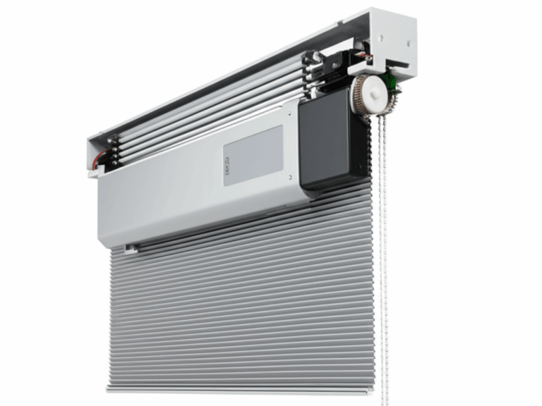
So, what exactly is this box we’re talking about? A motor starter is essentially a heavy-duty switch with a brain. Its main job is to safely start and stop a motor but, more importantly, it’s the motor’s personal bodyguard.
Why can’t you just use a simple light switch? Well, when a motor first starts, it draws a massive amount of current—way more than it needs to run. This inrush can damage the motor windings and trip a standard circuit breaker. A motor starter is built to handle that surge.
But its most critical role, in my opinion, is overload protection. It constantly monitors the current the motor is using. If the motor gets stuck, is overloaded, or starts to overheat, the starter detects the extra current draw and cuts the power before your motor turns into a very expensive paperweight. I’ve seen it happen. Statistics show that a staggering 70-80% of motor failures come from overheating, and a properly installed starter is your best defense.
Inside the starter, you’ll typically find two main parts:
Together, they provide a safe and controlled way to operate your equipment.
Safety First: Essential Precautions Before You Start
Before you even think about picking up a screwdriver, we need to talk about safety. This is the part of the job you can’t afford to skip. Electricity doesn’t give second chances, and I’ve heard too many horror stories. The data from OSHA is sobering, with hundreds of electrical fatalities every year in the US alone. Many of these are because someone thought the power was off when it wasn’t. Don’t be a statistic.
Here’s my non-negotiable safety checklist:
- De-energize the Circuit: Go to the electrical panel and turn off the circuit breaker that feeds the motor. Don’t just flip it. Put a piece of tape over it and a note that says “DO NOT TURN ON – WORK IN PROGRESS.” This is called Lockout/Tagout (LOTO), and it’s a life-saving habit.
- Verify Zero Voltage: This is the most crucial step. Never trust that the breaker is off. Never trust a label. Always verify. Take your voltage tester or multimeter and carefully check for voltage at the wires where you’ll be working. Test between L1 and L2 (or L1 and Neutral), and test each line to ground. You should read ZERO volts. I always test my meter on a known live outlet first to make sure it’s working, then test the dead circuit, then test the live outlet again. It’s a simple process that guarantees your meter is reliable.
- Wear Your PPE: Put on your safety glasses. You never know when a stray wire could poke you in the eye or a screw could fly off. I also recommend wearing insulated gloves, especially when you’re verifying for zero voltage.
- Know Your Codes: Check your local electrical codes. In the U.S., the National Electrical Code (NEC) provides the standards for safe electrical installations. A quick search can tell you about requirements for wire sizing, conduit, and grounding in your area.
Tools and Materials You’ll Need
Having the right tools ready before you start makes the job go so much smoother. There’s nothing worse than being halfway through a connection and realizing you’re missing something.
My Go-To Tool Kit:
- Screwdrivers: You’ll need a couple of different sizes, both flathead and Phillips head. A dedicated terminal screwdriver is great for getting a snug fit on those small control wires.
- Wire Strippers: A good pair of strippers is essential for clean, precise cuts without nicking the copper conductor.
- Lineman’s Pliers: For cutting heavier gauge wire and twisting conductors together.
- Multimeter/Voltage Tester: As I said, this is non-negotiable for safety. It’s also invaluable for troubleshooting later.
- Continuity Tester: Great for checking your control circuit before you apply power.
Essential Materials:
- The Motor Starter: Make sure it’s correctly sized for your motor’s voltage and horsepower (HP) or Full Load Amp (FLA) rating. This info is on the motor’s nameplate.
- The Motor: The reason we’re here!
- Electrical Wire: Use the correct gauge wire for your motor’s amperage and the distance from the panel. Undersized wires are a fire hazard. The NEC has tables to help you choose the right size.
- Conduit and Fittings: If you’re running wires in an exposed area, you’ll need conduit to protect them.
- Mounting Hardware: Screws or bolts to securely attach the starter enclosure to a wall or frame.
- The Wiring Diagram: Your starter and motor should both come with one. This is your road map. Don’t lose it!
Understanding the Single Phase Motor Starter Components
Let’s open up that starter box and get familiar with the key players. It can look a little intimidating at first, but once you understand what each part does, it all makes sense.
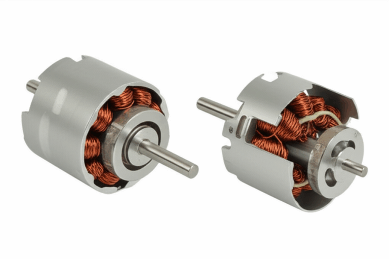
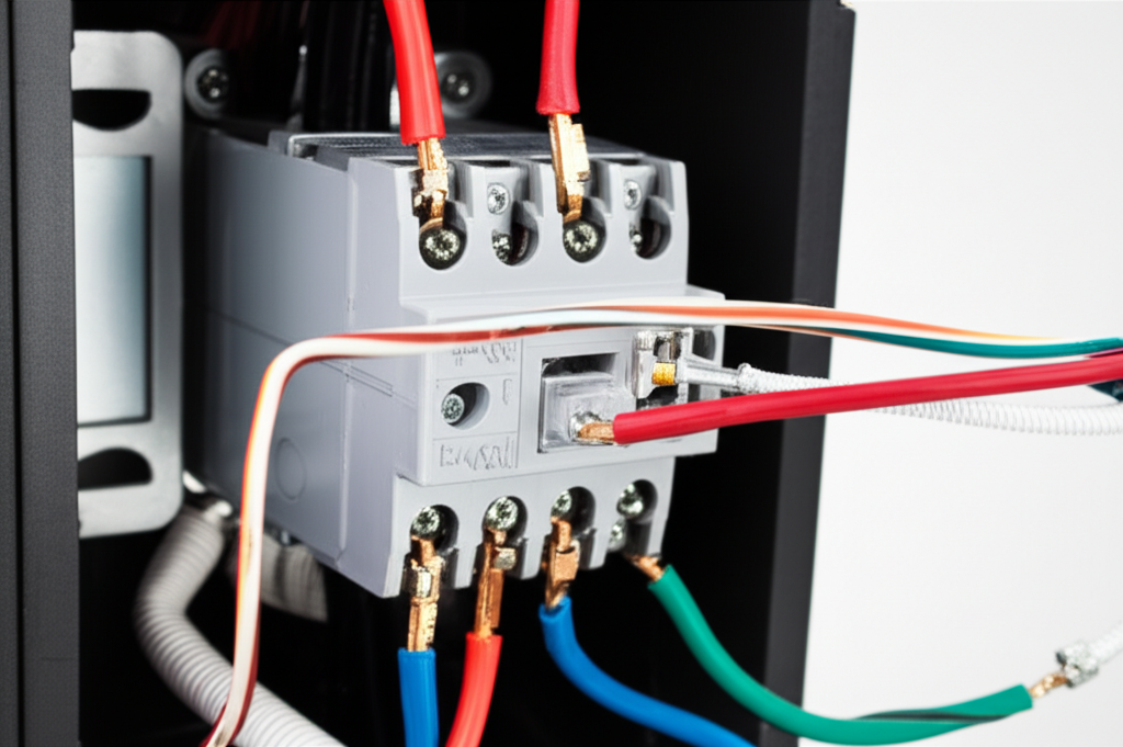
- The Contactor: Think of this as the big, strong heart of the starter. It has a set of main power terminals, usually labeled L1 and L2 for the incoming power, and T1 and T2 for the wires going out to the motor. When a small electrical signal is sent to its coil, it creates a magnetic field that slams a set of contacts shut, completing the circuit and sending full power to the motor. The basic motor principle relies on these magnetic fields to create motion.
- The Thermal Overload Relay: This is the protector. It’s usually attached directly to the T1/T2 side of the contactor. The motor wires pass through it. Inside are “heaters” that warm up as current flows. If the motor draws too much current for too long (an overload condition), these heaters get hot enough to trip a switch, which breaks the control circuit and tells the contactor to open, stopping the motor. You’ll need to set the amperage on the overload relay to match the motor’s FLA rating on its nameplate.
- Pushbutton Station (Start/Stop): This is how you tell the starter what to do.
- The Start button is a “Normally Open” (NO) switch. When you press it, it completes a circuit.
- The Stop button is a “Normally Closed” (NC) switch. It’s always completing a circuit until you press it, which breaks the circuit. This is a safety feature—if a wire to the stop button breaks, the circuit fails “off.”
- Auxiliary Contacts: These are smaller contacts attached to the side of the main contactor. They open and close along with the main contacts but are used for control logic, not for powering the motor. The most important one is a Normally Open (NO) contact that we’ll use to create the “holding circuit.”
Step-by-Step Connection Guide: Power & Control Circuits
Alright, let’s get to the main event. We’re going to wire this in two stages: the high-voltage Power Circuit and the low-voltage (or at least lower-amperage) Control Circuit.
Step 5.1: Mounting the Motor Starter
First things first, find a good home for your starter. Choose a spot that’s clean, dry, and easy to access but where it won’t get bumped or damaged. Securely mount the enclosure to a solid surface. Make sure there’s enough room around it to run your conduits and open the door fully.
Step 5.2: Connecting the Power Circuit (Main Voltage)
The power circuit is the superhighway for electricity. It carries the full load current from your panel to the motor.
Step 5.3: Wiring the Control Circuit (Start/Stop Logic)
The control circuit is the nervous system. It uses a much lower current to tell the contactor’s coil when to turn on and off. This is where most people get tripped up, but I’ll break it down.
Imagine you’re building a path for a small trickle of electricity. The path must be complete for the starter to turn on.
- From the same terminal on the Start button where you just landed, connect another wire. Run this wire to one side of a Normally Open (NO) auxiliary contact on the side of the contactor.
- Now, connect a wire from the other side of the Start button to the other side of that same NO auxiliary contact.
- Finally, from this same point (the output of the Start button and the output of the auxiliary contact), run a wire to one side of the contactor’s coil, usually marked A1.
What have we done here? We’ve created two parallel paths to the coil: one through the Start button and one through the auxiliary contact. When you press Start, power flows to the coil and the contactor pulls in. The moment it pulls in, the auxiliary contact closes, creating a new, permanent path for the power. When you release the Start button, the power keeps flowing through the auxiliary contact, “holding” the starter on. Brilliant!
When you press the Stop button, you break the entire path, the coil de-energizes, the contactor opens, and the auxiliary contact opens, resetting the whole circuit until you press Start again.
Post-Installation Checks and Testing
You’ve connected all the wires. It looks great. But don’t turn on the power just yet. I’ve learned the hard way that a few minutes of checking can save hours of headaches.
- The “Tug Test”: Go back to every single screw terminal and give the wire a gentle tug. If it’s loose, tighten it down. A loose connection in the power circuit can cause overheating and arcing. A loose connection in the control circuit will cause intermittent problems that are a nightmare to diagnose.
- Visual Inspection: Look over everything. Are any wires pinched? Is any copper exposed where it shouldn’t be? Does everything match the wiring diagram?
- Continuity Test (Power Off!): Use your multimeter’s continuity setting. With the power OFF, check that your control circuit works.
- Put one probe on the wire coming from L1 to the overload and the other on the wire going into the Stop button. You should have continuity.
- Press the Stop button. Continuity should break.
- Check across the Start button. It should be open until you press it.
- Power Up Safely: Clear the area. Put the cover on the starter. Stand to the side of the panel, not in front of it, when you flip the breaker on.
- Functional Test:
Common Troubleshooting for Single Phase Motor Starters
Even with a perfect installation, you can run into issues. Here are the most common problems I’ve encountered and how I solve them. This is where having experience with a general motor problem comes in handy.
- Motor Doesn’t Start (No Hum, No Click): This is almost always a control circuit issue.
- Is the overload relay tripped? Check the reset button.
- Is your Stop button stuck or wired incorrectly?
- Use your multimeter to check for control voltage. Do you have power at A1 when you press start? If not, trace the circuit back step-by-step.
- Motor Hums But Doesn’t Start: This is usually a motor or power circuit problem.
- Check your incoming voltage at L1 and L2. Is it too low?
- The problem could be a bad start capacitor on the motor itself.
- Is the mechanical load on the motor jammed? Try turning the shaft by hand (with the power OFF!).
- It’s possible one of the main contactor poles isn’t making good contact.
- Starter Clicks But Won’t Stay Engaged: Ah, the classic holding circuit problem. When you let go of the Start button, it dies. 99% of the time, this means there’s a problem with the wiring to your auxiliary contact. Double-check those two wires.
- Breaker Trips Immediately: This indicates a dead short. POWER OFF IMMEDIATELY. Check for a wire that’s landed in the wrong place or a conductor that’s touching the metal enclosure. This can also be caused by serious internal motor issues, where the integrity of the stator core lamination is compromised.
Frequently Asked Questions (FAQs)
Q: Can I connect a single-phase motor directly without a starter?
A: For very small motors (like under 1/2 HP), you sometimes can use a heavy-duty switch, but you lose the critical overload protection. For anything substantial, I would never recommend it. You’re risking a very expensive motor for the sake of saving a few dollars on a starter. It’s just not worth it.
Q: What size motor starter do I need?
A: Starters are sized based on horsepower (HP) and voltage. They also have a maximum amperage rating. You need to choose a starter that meets or exceeds the specs on your motor’s nameplate. Don’t guess.
Q: What’s the difference between a manual and magnetic starter?
A: A manual starter is just a switch with overload protection. You physically move a lever to start and stop it. A magnetic starter, which is what we’ve been discussing, uses a contactor and coil, allowing for remote control with pushbuttons, pressure switches, or float switches.
Q: How do I set the overload relay current?
A: Look for the “FLA” (Full Load Amps) on your motor’s nameplate. Set the dial on the overload relay to that exact number. Don’t set it higher thinking you’ll prevent nuisance trips—you’ll just be disabling its ability to protect your motor.
Q: Why is grounding so important?
A: I’ll say it again: grounding is a life-saving safety feature. It provides a path for fault current to travel safely to the ground, tripping the breaker. Without it, the metal frame of your motor or starter could become live with deadly voltage, waiting for someone to touch it.
Conclusion: Safe and Reliable Motor Operation
Wiring a single-phase motor starter might seem complex, but by breaking it down into the power and control circuits and following a logical, step-by-step process, it’s a very manageable task. The key is to be methodical, double-check your work, and prioritize safety above all else.
Remember to de-energize and verify, follow your wiring diagram, and test your connections. Taking your time with the installation will reward you with a system that runs safely and reliably for years to come. You’ll not only protect your motor but also ensure the safety of everyone who operates the equipment.
If you ever feel unsure or out of your depth, there is no shame in calling a licensed electrician. It’s always better to be safe than sorry.