How to Safely Reverse a Single Phase Motor with a Switch
Ever found yourself with a piece of equipment—a conveyor, a lathe, or even a heavy-duty fan—that would be infinitely more useful if it could just run in the opposite direction? You’re not alone. Many design engineers and hands-on technicians face the challenge of controlling the rotational direction of single-phase motors. If you’ve been searching for a reliable, safe method to add forward and reverse functionality to your machinery, you’re in the right place.
This guide is designed to be your trusted engineering partner, walking you through the principles, safety protocols, and step-by-step wiring instructions needed to reverse a single-phase motor using a switch. We’ll demystify the process, explain the “why” behind the “how,” and empower you to tackle this common but critical task with confidence.
What We’ll Cover
- Essential Safety Precautions: The non-negotiable first steps before you touch a single wire.
- Understanding Motor Basics: A simple breakdown of how single-phase motors work and the core principle of reversal.
- Tools and Materials: The checklist of everything you’ll need for the job.
- Step-by-Step Wiring with a DPDT Switch: The detailed, practical guide to making the connections.
- Using a Drum Switch: An alternative, robust solution for motor control.
- Key Considerations for Success: Important factors to ensure a safe and long-lasting modification.
- Troubleshooting Common Issues: What to do when things don’t go as planned.
Essential Safety Precautions Before You Start
Let’s get the most important thing out of the way first. Working with electrical power is inherently dangerous. A simple mistake can lead to severe injury, electrocution, or fire. Before you even think about opening a motor’s terminal box, you must follow these safety procedures without exception.
🔴 WARNING: RISK OF SEVERE ELECTRICAL SHOCK! 🔴
- Disconnect All Power: This is not optional. Unplug the motor from the wall outlet or switch off the corresponding circuit breaker at the main electrical panel. Don’t just rely on the machine’s power switch.
- Implement Lockout/Tagout (LOTO): In an industrial setting, apply a lock and tag to the circuit breaker or plug. This prevents anyone from accidentally re-energizing the circuit while you’re working on it. Even in a home workshop, a simple sign on the breaker or unplugged cord can prevent a dangerous surprise.
- Verify Power is OFF: Trust, but verify. Use a multimeter or a non-contact voltage tester to confirm that there is zero voltage present at the motor terminals where you’ll be working. Test your meter on a known live circuit first to ensure it’s working correctly.
- Wear Appropriate Personal Protective Equipment (PPE): At a minimum, wear safety glasses to protect your eyes from debris or sparks. Insulated gloves provide an essential layer of protection against accidental shock.
- When in Doubt, Consult a Professional: If you feel uncertain at any point, or if your motor’s wiring doesn’t match the diagrams you find, stop immediately. It’s always better to consult a qualified electrician than to risk your safety or damage your equipment.
Understanding Single Phase Motor Basics and Reversal Principle
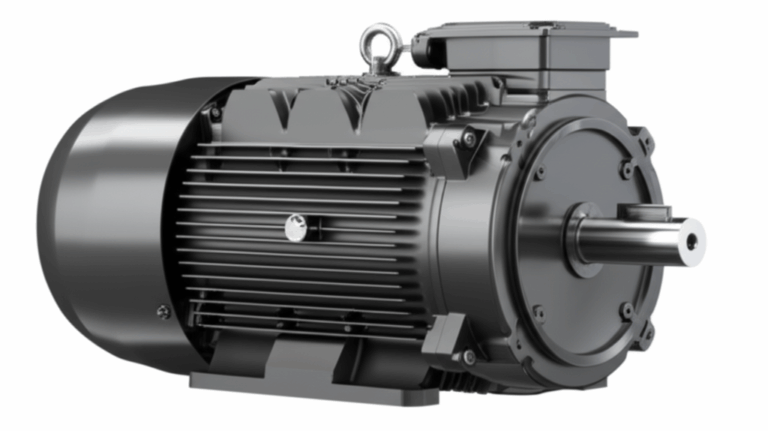
To successfully reverse a motor, you first need to understand a little bit about how it works. Think of it like learning the basic rules of a game before you try to change the outcome. The operation of most single-phase AC induction motors, the kind you’ll find in everything from drill presses to HVAC fans, hinges on the interaction between two sets of wire coils, or “windings.”
These are the main players:
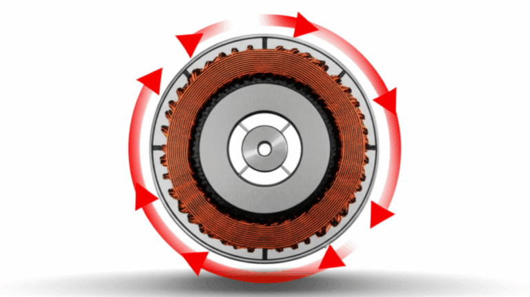
Here’s the magic: a single-phase motor can’t start on its own because the magnetic field from the run winding just pulses back and forth. It needs a “nudge” to get it going one way or the other. The start winding provides this nudge. By creating a second magnetic field that’s out of sync (out of phase) with the main one, it creates a weak rotating magnetic field—just enough to give the rotor a decisive push and set its direction.
The Golden Rule of Reversal: To reverse the motor’s direction, you must reverse the polarity of the start winding relative to the run winding.
That’s it. It’s that simple in principle. You are essentially changing the timing of that initial “nudge,” telling the rotor to start spinning in the opposite direction. You can achieve the same result by reversing the run winding’s polarity while leaving the start winding alone, but the standard and most common practice is to reverse the start winding.
What happens if you reverse both? Nothing. If you swap the connections on both windings, you’ve flipped the entire magnetic field system together. The relationship between the two fields remains the same, and the motor will continue to run in its original direction.
Different Motor Types and Their Nuances
While the principle is universal, the exact wiring can differ slightly. Here are a few common types:
- Split-Phase Motors: The simplest type. They use the start and run windings and a centrifugal switch.
- Capacitor-Start Motors: These are very common. They add a start capacitor in series with the start winding. This capacitor gives the motor a much stronger starting “kick” or torque, which is great for hard-to-start loads.
- Permanent Split Capacitor (PSC) Motors: These use a run capacitor that stays in the circuit all the time. They don’t have a centrifugal switch, which makes them quieter and more reliable. Reversing them often involves swapping connections on the capacitor.
- Universal Motors: Found in power tools and appliances, these motors have brushes and can run on AC or DC power. They are typically the easiest to reverse—you simply swap the polarity of the field winding or the armature, but not both.
The first step is always to identify your motor’s windings. Look for a wiring diagram on the motor’s nameplate or on the inside of the terminal box cover. The terminals are often labeled (e.g., T1, T2, T5, T8). If there’s no diagram, you’ll need to use a multimeter to identify the windings through resistance testing (the start winding usually has a higher resistance than the run winding).
Tools and Materials You’ll Need
Gathering your tools beforehand makes the job smoother and safer. Here’s a typical checklist:
- Reversing Switch:
- DPDT (Double Pole, Double Throw) Switch: A center-off DPDT switch is ideal. It has six terminals and allows you to completely reverse the current flow through a circuit. Make sure it’s rated for your motor’s voltage and amperage.
- Drum Switch: A more heavy-duty, purpose-built switch for motor control, often with clearly marked terminals for forward and reverse.
- Wire Strippers: To cleanly remove insulation from wires.
- Screwdriver Set: You’ll need both flathead and Phillips head screwdrivers for terminal screws.
- Multimeter: Absolutely essential for verifying power is off and for identifying motor windings if needed.
- Insulated Wire: A small amount of stranded wire, with an insulation rating and gauge (thickness) appropriate for the motor’s voltage and current.
- Wire Connectors: Wire nuts or crimp connectors to ensure secure, insulated connections.
- Electrical Tape: For added insulation and to keep wiring tidy.
- The Motor’s Wiring Diagram: This is your most critical tool. Do everything you can to find it.
Step-by-Step Guide: Reversing a Single Phase Motor with a DPDT Switch
This is where the theory meets practice. We’ll use a common capacitor-start motor with four external leads as our example.
What is a DPDT Switch and How Does it Work?
Imagine a DPDT switch as two separate light switches that are mechanically linked to a single lever. “Double Pole” means it can control two separate circuits at once. “Double Throw” means each circuit can be connected to one of two different outputs.
For our purpose, it’s a perfect polarity-reversing tool. In one position, it sends power through the start winding one way. In the other position, it sends it through the other way, effectively flipping the positive and negative connections. A center-off position is highly recommended as it provides a clear “stop” state.
General Wiring Diagram Principle
Here’s the game plan:
Detailed Wiring Steps
Let’s get down to the connections.
1. Disconnect Power: We can’t say it enough. Make sure the motor is completely de-energized and verified with your multimeter.
2. Identify Motor Terminals: Open the motor’s terminal box. You should see several wires. Based on the motor’s diagram, identify the two leads for the run winding and the two leads for the start winding. For this example, let’s assume you have four leads:
- Run Winding: Wires T1 and T4
- Start Winding: Wires T5 and T8
3. Prepare the Switch and Wires: On a DPDT switch, you have two rows of three terminals. The center terminals are the “common” inputs. The outer terminals are the outputs.
- Create two small “X” jumpers out of wire. Connect a jumper from the top-left terminal to the bottom-right terminal.
- Connect the second jumper from the top-right terminal to the bottom-left terminal. This “X” configuration is the key to reversing the polarity.
4. Connect Power to the Switch:
- Connect the incoming Hot wire (usually black) to one of the center common terminals.
- Connect the incoming Neutral wire (usually white) to the other center common terminal.
5. Wire the Switch to the Motor Windings:
- Run Winding: The run winding gets wired in parallel with the incoming power. Connect one run winding lead (T1) to the Hot wire connection point. Connect the other run winding lead (T4) to the Neutral wire connection point. (Often, you’ll make these connections at the same terminals where the main power feeds the switch).
- Start Winding: This is where the switch does its work.
- Connect one start winding lead (T5) to one of the top terminals of the switch (e.g., top-left).
- Connect the other start winding lead (T8) to the other top terminal (e.g., top-right).
- If there’s a start capacitor, it must remain in series with the start winding. Usually, you’d connect T5 to one side of the capacitor, and the other side of the capacitor to the switch terminal.
6. Secure and Verify All Connections:
- Gently tug on each wire to ensure it’s secure in its terminal or wire nut.
- Cover all exposed connections with electrical tape or use a proper junction box.
- Double-check your wiring against your motor’s specific diagram. The fundamental connection—reversing the start winding leads through the “X” on the switch—is what matters. The integrity of the motor core laminations is essential for efficient magnetic field generation, so ensure all connections are tight to avoid vibrations that could damage them over time.
7. Test Safely:
- Clear the area around the motor shaft.
- Stand back, restore power at the breaker, and briefly flip the switch to one position. Observe the rotation.
- Turn the switch to the center “off” position and wait for the motor to come to a complete stop.
- Flip the switch to the other position and verify that the motor now spins in the opposite direction.
Alternative: Reversing with a Dedicated Drum Switch
For more industrial or high-use applications, a drum switch is often a better choice.
- Advantages: These switches are built for the abuse of a workshop. They are more robust, often have a more positive feel, and are specifically designed for motor control, with terminals clearly labeled “Forward” and “Reverse.”
- Wiring Principle: The internal mechanics of a drum switch accomplish the exact same polarity reversal as our DPDT setup, but the connections are often more straightforward. You typically connect the incoming line power and the four motor leads directly to terminals on the switch.
- Installation: Always follow the wiring diagram that comes with the drum switch. It will show you exactly where to land the run winding leads, the start winding leads, and the incoming power lines.
Key Considerations for Successful and Safe Reversal
Modifying your motor’s control system requires attention to detail. Here are some key engineering considerations to keep in mind:
- Always Consult Your Motor’s Wiring Diagram: This is your single source of truth. A generic guide is helpful, but the manufacturer’s diagram for your specific motor model is gospel. It accounts for the unique internal motor principle of your device.
- Capacitor Management: Start capacitors are designed for momentary use—just a few seconds during startup. Rapidly reversing the motor without letting it stop can keep the start circuit engaged for too long, causing the capacitor to overheat and fail.
- Avoiding Rapid Reversals (“Plugging”): Instantly reversing a spinning motor puts immense mechanical stress on the motor shaft, bearings, and the connected machinery. It also causes a huge electrical current surge. Unless the motor and application are specifically designed for it, always allow the motor to come to a complete stop before reversing direction.
- Overload Protection: Your motor’s original circuit should have overload protection (heaters or a protective device). Ensure this protection remains correctly wired and functional after your modification.
- Voltage and Current Ratings: The switch you choose must be rated for the motor’s operating voltage and its Full Load Amperage (FLA), which you can find on the nameplate. An underrated switch will fail, creating a serious fire hazard.
To put these risks into perspective, here is a summary of practical data to consider.
Table: Practical Data & Considerations for Single-Phase Motor Reversal
| Category | Data Point / Consideration | Relevance to Reversal | Implications for User |
|---|---|---|---|
| Safety Risks | Electrical Shock/Electrocution: Around 1,000 non-fatal electrical accidents occur annually in US workplaces. | Improper wiring is a leading cause. | CRITICAL: Always disconnect and verify power. Incorrect wiring during reversal attempts significantly increases risk. |
| Motor Damage | Rapid Reversals: Can cause severe stress on windings, bearings, and mechanical components. | Frequent, uncontrolled reversals shorten motor lifespan. | Implement safety interlocks or time delays. Always allow the motor to come to a full stop before reversing. |
| Common Wiring Errors | Incorrect Winding Polarity: Attempting to reverse both main and start windings simultaneously. | The motor will not reverse, will just hum, or may overheat. | Meticulously follow wiring diagrams. Ensure only the start (or auxiliary) winding polarity is reversed relative to the main winding. |
| Component Compatibility | Switch Rating: The switch must match or exceed the motor’s Full Load Amperage (FLA) and voltage. | An underrated switch can overheat, weld its contacts shut, or fail catastrophically. | Check the motor nameplate for FLA and voltage. Select a switch with appropriate ratings (e.g., 20A, 250V for a 1.5 HP 120V motor). |
| Motor Type Variation | Internal Wiring Differences: Split-phase, capacitor-start, PSC, and universal motors have distinct wiring. | General guides may not apply to all types without modification. | Always consult the specific motor’s wiring diagram. Reversing a PSC motor often involves the capacitor, while a universal motor reverses by switching armature or field leads. |
| Capacitor Impact | Start Capacitor Overload: Rapid reversals can cause the start capacitor to fail. | Start capacitors are designed for momentary use only. | Ensure the centrifugal switch (if present) operates correctly. Avoid any scenario that keeps the start winding energized continuously. |
Troubleshooting Common Reversal Issues
Even with careful work, you might run into a snag. Here are some common problems and their likely causes.
- Motor Hums But Doesn’t Start or Reverse: This classic symptom usually points to a problem in the start winding circuit.
- Check your wiring: Double-check that the start winding is correctly wired through the switch.
- Bad Capacitor: The start capacitor may have failed.
- Centrifugal Switch: The internal centrifugal switch might be stuck open, preventing the start winding from ever getting power. Any serious internal issue might indicate a fundamental motor problem that wiring can’t fix.
- Motor Runs in Only One Direction:
- Incorrect Switch Wiring: Most likely, the “X” jumpers on your DPDT switch are missing or wired incorrectly, so it’s not actually reversing the polarity.
- Faulty Switch: The switch itself could be defective on one side.
- Motor Overheats:
- Stuck Centrifugal Switch: If the switch gets stuck in the closed position, it keeps the start winding energized. This winding isn’t designed for continuous duty and will quickly overheat, potentially burning out. You’ll often hear a distinct hum.
- Incorrect Wiring: A miswired connection could be causing excessive current draw.
- Overload: The load connected to the motor may be too heavy.
- Blown Fuse or Tripped Breaker:
- Short Circuit: You may have a direct short between the hot and neutral wires in your new wiring. Re-check all connections carefully.
- Starting Current: Reversing the motor while it’s still spinning can create a current spike large enough to trip a breaker. The complex interplay between the stator and rotor during a rapid reversal generates this surge.
Conclusion: Master Your Motor’s Direction
Adding a reversing switch to a single-phase motor is a powerful upgrade that can dramatically improve the functionality of your equipment. While the task requires a healthy respect for electricity and careful attention to detail, the underlying principle is straightforward: change the relationship between the start and run windings, and you change the direction of rotation.
By prioritizing safety, using your motor’s wiring diagram as your guide, and methodically checking your connections, you can confidently and successfully master your motor’s direction. You’ve moved beyond simply using a tool to understanding and controlling it—a hallmark of true engineering skill.
Remember the key takeaways:
- Safety first, always. Disconnect and verify.
- Reverse one winding only—typically the start winding.
- Your motor’s diagram is your best friend.
- Use components rated for the job.
Now you have the knowledge to not only solve this engineering problem but to do it safely and effectively.