How to Safely Wire a 220V Single Phase Motor: A Comprehensive Step-by-Step Guide
Here’s a comprehensive guide on how to wire a 220V single-phase motor, written from a first-person perspective and adhering to all the specified guidelines.
I remember the first time I bought a serious piece of equipment for my workshop—a big 240V air compressor. It arrived on a pallet, and I was thrilled until I looked at the bare wires hanging from the motor. That’s when it hit me: I had to wire this thing myself. The idea of working with 220V (or 240V, they’re often used interchangeably) was intimidating. But after some careful research, talking to an electrician friend, and taking it one step at a time, I got it done safely and correctly.
Since then, I’ve wired dozens of single-phase motors for everything from table saws and dust collectors to pumps and grinders. I’ve learned what to look for, what to avoid, and how to do it right every time.
This guide is everything I wish I had back then. I’m going to walk you through the entire process, step-by-step, just like I would if I were right there in the shop with you. We’ll cover the safety essentials, the tools you need, how to read that confusing motor nameplate, and the exact steps to get your motor humming happily.
Table of Contents
- I. First Things First: Understanding Your 220V Single Phase Motor
- II. Essential Safety: Before You Touch a Single Wire
- III. Gathering Your Tools & Materials
- IV. Decoding Your Motor’s Nameplate & Wiring Diagram
- V. Step-by-Step Wiring Procedure: The Main Event
- VI. The Moment of Truth: Testing and Verification
- VII. Common Problems & How to Fix Them
- VIII. When to Hang Up Your Tools and Call a Pro
- IX. Final Thoughts: Powering Up with Confidence
I. First Things First: Understanding Your 220V Single Phase Motor
Before we get our hands dirty, let’s quickly cover what we’re working with. A single-phase 220V motor is the workhorse of many home workshops, farms, and small businesses. You’ll find them on big table saws, air compressors, hydraulic pumps, and large fans.
So, why 220V instead of the standard 110V/120V outlet? It’s all about efficiency. A motor running on 220V draws half the amperage (current) as the same motor running on 110V to produce the same amount of power (horsepower). Lower amps mean you can use smaller-gauge wires, and the motor tends to run cooler and more efficiently, which translates to a longer life. The basic motor principle involves using magnetism to create rotation, and doing so at a higher voltage is simply more effective for powerful tools.
Getting the wiring right isn’t just about making the motor turn on. It’s about:
- Safety: This is number one. 220V is unforgiving. A mistake can lead to a nasty shock, a fire, or a destroyed motor.
- Performance: Correct wiring ensures your motor delivers the power it’s rated for without struggling or overheating.
- Longevity: A properly wired and protected motor can last for decades. A poorly wired one might not last the day.
In this guide, I’ll show you how to do it safely so you can get your equipment up and running with confidence.
II. Essential Safety: Before You Touch a Single Wire
I cannot stress this enough: electricity is dangerous. If you feel even slightly unsure about what you’re doing, please stop and call a qualified electrician. It’s not worth the risk. But if you’re comfortable and ready to proceed, you absolutely must follow these safety rules. No shortcuts. Ever.
A. Personal Protective Equipment (PPE)
This is non-negotiable. At a minimum, you need:
- Safety Glasses: Wires can poke you in the eye, and you never know when a stray spark might fly. Always protect your vision.
- Insulated Gloves: While you should never work on a live circuit, wearing electrician’s gloves provides an extra layer of protection against accidental shock.
- Appropriate Clothing: Avoid loose or frayed clothing that can get snagged. Wear sturdy shoes, preferably with rubber soles.
B. Lockout/Tagout (LOTO) Procedures
This is a professional process that you should adopt in your own shop. The idea is to make it physically impossible for the circuit to be energized while you’re working on it.
Even after all this, you still must test that the power is off at the point of connection.
C. Electrical Hazards & Risks
You need to be aware of what can go wrong:
- Electric Shock: Direct contact with 220V can be fatal.
- Arc Flash: If you accidentally short-circuit the wires, it can create a brilliant, explosive flash of energy that can cause severe burns and damage your eyes.
- Fire: Overheating from loose connections or undersized wires is a major fire hazard.
D. Code Compliance (NEC/Local Codes)
The National Electrical Code (NEC) provides the minimum safety standards for wiring. Your local area might have additional rules. Following the code isn’t just about passing an inspection; it’s about ensuring a safe and reliable installation. We’ll be touching on code-compliant practices throughout this guide, like using the right wire size and proper grounding.
III. Gathering Your Tools & Materials
Having the right gear makes the job easier and safer. Here’s a checklist of what I keep in my bag for a motor wiring job.
Essential Tools:
- Multimeter: This is your most important safety tool. You’ll use it to verify that the power is OFF before you start and to check for continuity later. A simple non-contact voltage tester isn’t enough; you need a multimeter to confirm zero voltage.
- Wire Strippers: Get a good pair that can handle the gauge of wire you’re using.
- Screwdrivers: You’ll need both flathead and Phillips head screwdrivers, and often a set of nut drivers for terminal connections.
- Pliers: A good set of lineman’s pliers for cutting heavy wire and needle-nose pliers for detail work is invaluable.
Wiring & Connection Components:
- Wire (Conductor): The size, or gauge, of the wire is critical. It must be thick enough to handle the motor’s current draw (amperage). Check your motor’s nameplate for the Full Load Amps (FLA) and consult an ampacity chart (you can find these online based on NEC standards). For most home shop 220V motors (up to 3-5 HP), 12-gauge or 10-gauge wire is common, but always verify.
- Conduit and Fittings: If you’re running the wire along a wall, you need to protect it. Conduit (like EMT for indoors or PVC for damp locations) is the professional way to do it.
- Junction Box: If you’re not wiring directly into a motor starter, you’ll need a junction box to safely contain the wire connections.
- Connectors: Use high-quality wire nuts or crimp connectors rated for your wire size.
- Motor Starter / Disconnect Switch: For larger motors, a simple switch isn’t enough. A motor starter combines a heavy-duty contactor to handle the electrical load with overload protection. This is highly recommended and often required by code. A simple disconnect switch provides a safe way to kill power right at the machine.
- Circuit Breaker: Make sure the breaker in your panel is correctly sized for the circuit. It should be large enough to handle the motor’s startup surge but small enough to trip if there’s a real fault. Again, this is determined by the motor’s FLA and NEC guidelines.
IV. Decoding Your Motor’s Nameplate & Wiring Diagram
The motor’s nameplate is its instruction manual. It tells you everything you need to know. It can look like a bunch of gibberish at first, but it’s pretty simple once you know what you’re looking for.
- VOLTS (V): This should say something like 208-230/460 or 115/230. Since you’re wiring for 220V, you’ll use the “230V” configuration. A dual-voltage motor will have different wiring instructions for each voltage.
- AMPS / FLA (Full Load Amps): This is the maximum current the motor will draw under its rated load. This is the most important number for selecting your wire size and overload protection.
- HP (Horsepower): This is the mechanical output power of the motor.
- RPM (Revolutions Per Minute): This is the speed of the motor’s shaft.
- SF (Service Factor): A service factor of 1.15 means the motor can occasionally handle a 15% overload. A 1.0 SF means it has no extra capacity.
- FRAME: This is a standardized number for the motor’s physical dimensions, like the mounting bolt pattern.
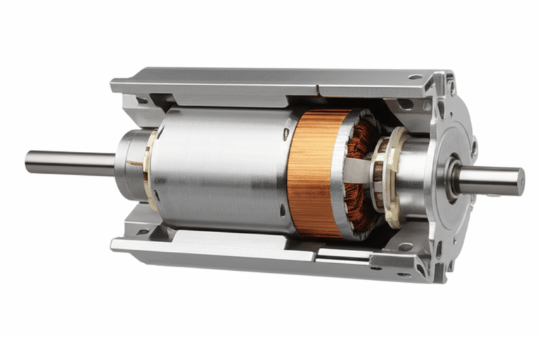
- WIRING DIAGRAM: This is the treasure map! It’s usually a sticker on the motor itself or inside the cover of the terminal box. It will show you exactly which wires to connect for high voltage (220V/240V) or low voltage (110V/120V) operation, and often how to reverse the motor’s rotation. The internal components, like the stator and rotor, are precisely engineered, and this diagram ensures you power them correctly.
Take a picture of the wiring diagram with your phone before you start. Trust me, it’s a lifesaver.
V. Step-by-Step Wiring Procedure: The Main Event
Alright, let’s get down to business. We’ve done our homework, gathered our tools, and prioritized safety. Now it’s time to connect the wires.
Step 1: Disconnect Power & Verify Zero Voltage
I’m saying it again because it’s that important. Go to your electrical panel, turn off the correct breaker, and apply your lockout/tagout device. Now, go to where you’ll be connecting the motor. Use your multimeter, set to AC voltage, and test the wires you’ll be using. Touch one probe to one hot wire and the other to the ground. It should read 0. Then test the other hot wire to ground. It should read 0. Finally, test between the two hot wires. It should read 0. Only proceed when you have confirmed there is no voltage.
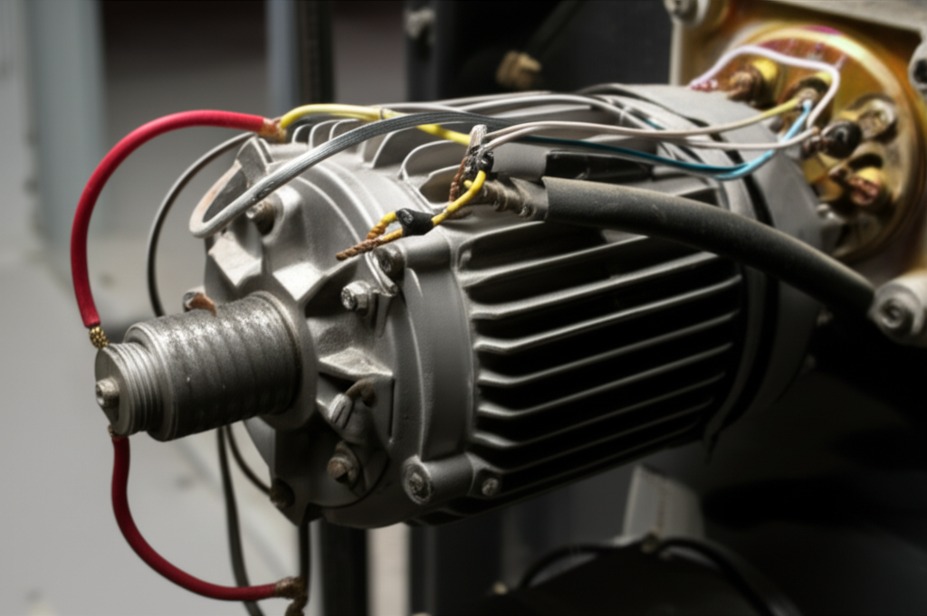
Step 2: Prepare the Motor Terminal Box
Most motors have a small metal box on the side where the wires come out. This is the terminal or junction box. Use a screwdriver to remove the cover. Inside, you’ll see a collection of wires (often labeled with numbers like T1, T2, T3, T4, etc.) and a grounding screw. The grounding screw is usually green or marked with the ground symbol (⏚).
Step 3: Run Power Supply Wires to the Motor Location
Run your correctly sized cable or individual wires inside conduit from your power source (a disconnect switch or junction box) to the motor’s terminal box. Make sure to use the proper connectors to secure the cable or conduit to the box. Leave yourself about 6-8 inches of extra wire inside the box to make connections easily.
Step 4: Connect the Ground Wire (The Lifesaver)
The ground wire is your primary safety feature. It provides a path for electricity to go to the earth in case of a short circuit, preventing the motor’s metal frame from becoming dangerously energized.
- Always connect the ground wire first.
- The ground wire from your power source (usually bare copper or green) connects directly to the green grounding screw inside the motor’s terminal box. Make sure the connection is tight and secure.
Step 5: Connect the Line (Hot) Wires to the Motor
Now for the power-carrying wires. In a 220V single-phase setup, you’ll have two “hot” wires (often called Line 1 and Line 2, or L1 and L2) and no neutral. The color code for these can vary, but commonly they are black and red, or sometimes two black wires.
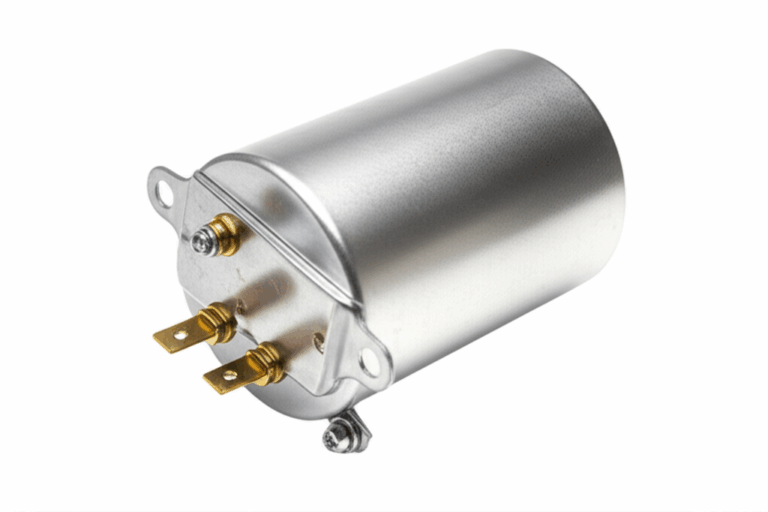
Step 6: Wiring Capacitors (If Applicable)
Many single-phase motors have one or two capacitors—those little cylinder-shaped things on the side.
- Start Capacitor: Gives the motor an extra jolt of torque just to get it spinning. It’s only in the circuit for a second, then a centrifugal switch disconnects it.
- Run Capacitor: Stays in the circuit the whole time to improve the motor’s efficiency and running torque.
If you’re replacing a capacitor, make sure the new one has the same microfarad (µF) and voltage rating. The wiring diagram will show you exactly where the capacitor wires connect, usually to the start and run windings.
Step 7: Wiring with a Motor Starter/Disconnect (Recommended)
For any motor that doesn’t have built-in overload protection, I strongly recommend using a manual motor starter. This device is a combination of a switch and an overload relay.
Step 8: Reversing Motor Rotation (Optional)
Does your motor spin the wrong way for your application? Don’t worry, it’s usually an easy fix. The motor’s wiring diagram almost always includes instructions for reversing rotation. Typically, it involves swapping two of the internal motor leads. For example, the diagram might say, “To reverse rotation, interchange leads T5 and T8.” Just make sure the power is completely off before making any changes.
Step 9: Secure Connections & Close Up
Once everything is connected, do a final check.
- Are all wire nuts tight?
- Is the ground screw secure?
- Are there any stray strands of copper that could cause a short?
Gently fold the wires into the terminal box, making sure not to pinch them when you put the cover back on. Tighten the cover screw, and you’re ready for testing.
VI. The Moment of Truth: Testing and Verification
This is the part that gets the heart pumping a little faster.
A. Pre-Power-Up Checks
Do one last visual inspection. Make sure no tools are left on the motor and that the motor’s shaft can spin freely. If it’s connected to a pump or a saw, ensure nothing is engaged.
B. Initial Power-Up (The “Bump Test”)
Stand clear of the motor. Remove your lockout/tagout device and turn the circuit breaker on.
Quickly turn the motor’s switch on and then immediately off again. This is just a “bump” to check two things:
If everything seems okay, you can proceed. If it hums but doesn’t start, or if it immediately trips the breaker, turn the power off, lock it out, and move to the troubleshooting section.
C. Monitoring During Operation
Now, turn the motor on and let it run for about 30 seconds. Listen for any strange grinding or scraping noises. Watch for excessive vibration. Place your hand carefully on the motor housing; it will get warm, but it shouldn’t get blazing hot in a short amount of time. If you have a clamp-on ammeter, now is a great time to check the current draw and compare it to the FLA on the nameplate.
VII. Common Problems & How to Fix Them
Even with careful work, sometimes things don’t go as planned. Here are a few common issues and what to check. When you encounter a persistent issue, it’s often a sign of a deeper motor problem that may require professional diagnosis.
- Motor Hums But Doesn’t Start:
- Bad Capacitor: This is the most common cause. The start capacitor provides the kick to get it going. If it’s failed, the motor won’t have enough torque to start.
- Centrifugal Switch: The internal switch that disconnects the start winding might be stuck open.
- Low Voltage: Check the voltage at the motor terminals while trying to start it. A significant drop can prevent it from starting.
- Motor Overheats:
- Overloaded: Is the motor working too hard? A blade that’s binding or a pump that’s clogged can cause an overload.
- Incorrect Voltage: A dual-voltage motor wired for 110V but connected to 220V will burn out quickly. Double-check your connections against the diagram.
- Poor Ventilation: The motor’s cooling fins need to be clean and have clear airflow around them.
- Motor Trips the Breaker:
- Short Circuit: This is a serious issue. Turn off the power immediately and re-check all your wiring for any crossed or bare wires touching the motor frame.
- Wrong Breaker Size: If the breaker is too small, the initial startup current of the motor might be enough to trip it. However, do not simply install a larger breaker without ensuring the wire gauge is appropriate for it.
- Locked Rotor: Something is physically preventing the motor shaft from turning.
VIII. When to Hang Up Your Tools and Call a Pro
I’m a huge fan of DIY, but it’s crucial to know your limits. You should absolutely call a licensed electrician if:
- You’re not 100% confident in what you’re doing.
- You need to install a new circuit or make changes inside your main electrical panel.
- The motor’s wiring diagram is missing or unreadable.
- After wiring it correctly, you’re still having problems like tripped breakers or overheating.
- You need the work to be inspected and approved for commercial or insurance purposes.
There’s no shame in calling for help. It’s the smart and safe thing to do.
IX. Final Thoughts: Powering Up with Confidence
Wiring a 220V single-phase motor might seem daunting, but it’s a very manageable task if you are methodical, patient, and, above all, safe. By understanding the components, carefully following the wiring diagram, and triple-checking your work, you can successfully power your equipment and have the satisfaction of knowing you did it yourself.
Remember the golden rule: Always turn off the power and verify it’s off before you touch anything. Take your time, trust the process, and you’ll have that new machine running smoothly in no time. Happy building