How to Safely Wire a 3-Phase Motor: A Comprehensive Guide (Diagrams & Steps)
- Table of Contents
- Introduction: How to Safely Wire a 3-Phase Motor
- What is a 3-Phase Motor and Why Does Wiring Matter?
- What Safety Steps Must You Take First?
- How Do You Read a Motor Nameplate With Confidence?
- Which Wiring Configuration Should You Use: Star or Delta or Dual Voltage?
- How Do You Wire a Motor to a DOL Starter Step by Step?
- How Do You Wire a Motor to a VFD the Right Way?
- What About Advanced Wiring Cases and Special Starters?
- How Do You Test Your Work and Start Up Safely?
- What Are Common Wiring Mistakes and How Do You Fix Them?
- What Tools and Materials Do You Need?
- How Do You Size Wires, Breakers, and Overloads?
- How Do You Ground and Route Cables the Right Way?
- Maintenance: How Do You Keep the Motor Healthy?
- When Should You Call a Pro and Check Codes?
- Why Do Quality Laminations Matter to Motor Life?
- References
- Key Points to Remember
Wiring a 3-phase motor can feel scary. I get it. High voltage can hurt you and it can ruin gear if you wire it wrong. In this clear guide I will show you how to wire a Three-Phase Induction Motor step by step. You will see wiring diagrams, simple checks, and smart tips. I will also show you how to wire to a Direct On-Line (DOL) Starter and a Variable Frequency Drive (VFD). Read on if you want safe work and a motor that starts right and runs strong.
What is a 3-Phase Motor and Why Does Wiring Matter?
A 3-phase motor uses three power wires that are spaced 120 degrees apart. That three-phase power gives smooth and strong torque. This is why plants use it for pumps, fans, conveyors, and more. A Three-Phase Power Supply runs the motor with steady pull. You get less vibration and more efficiency than with single phase. Many motors are fan cooled so they stay at safe heat.
Proper wiring is not just a neat task. It protects people and machines. Correct 3 phase motor wiring gives you the right motor rotation direction, the right line voltage at the terminal block, and the right overload protection. Bad wiring can cause shorts, trips, smoke, or worse. You also want code-safe work that meets NEC standards and IEC standards for safety and performance. That is how you prevent short circuit protection failures and fire risks.
This guide is a guide to 3 phase motor wiring that covers electrical wiring 3 phase motor basics and advanced cases. I will show 3 phase motor wiring diagrams, practical 3 phase wiring tips, and common 3 phase wiring mistakes to avoid. I will also touch on industrial 3 phase motor wiring, commercial 3 phase motor wiring, and even home 3 phase motor wiring for VFD jobs.
What Safety Steps Must You Take First?
Problem: People rush. They skip safety. They get hurt.
Agitate: A live wire does not care if you are new or pro. Shock and arc flash can kill. One mistake can end a life.
Solution: Slow down. Use a checklist. Use Lockout/Tagout (LOTO). Wear Personal Protective Equipment (PPE). Test for no voltage.
- Use LOTO. Put the lock on the disconnect switch. Tag it. Try to start the motor to verify it is off.
- Wear PPE. Use gloves and safety glasses. Use arc-rated gear when needed.
- Verify de-energized circuits. Use a Voltage Meter or Multimeter. Test the tester first on a known live point. Then test your circuit. Then test the tester again. Do not guess.
- Know the hazard. Learn arc flash basics from NFPA 70E. Follow electrical safety regulations in your area.
- Keep your space neat. Use insulated screwdrivers and keep tools away from live parts. Use wire strippers not a knife.
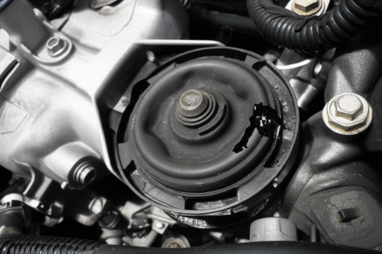
How Do You Read a Motor Nameplate With Confidence?
Your Motor Nameplate is your map. It shows key data:
- Voltage compatibility 3 phase motor
- Full Load Amps (FLA)
- Horsepower (HP) or Kilowatt (kW)
- RPM and Frequency (Hz)
- Service factor motor
- Motor insulation class
- Starting current (LRA)
- Motor frame size
- Enclosure types for motors and IP rating motor enclosure
- Nameplate data 3 phase motor for Star or Delta
- NEMA vs. IEC standards and approvals like UL and CSA
Check the connection diagram on the plate. It may show Star (Wye) connection or Delta connection. Some units are dual voltage 3 phase motor wiring designs. They may have 9 leads or 12 leads and can be wired for high or low voltage. This helps when you have high voltage 3 phase wiring like 460 V or low voltage 3 phase wiring like 208 to 240 V.
Which Wiring Configuration Should You Use: Star or Delta or Dual Voltage?
You will pick Star connection motor wiring or Delta connection motor wiring based on the supply and the motor. You may also see Wye connection 3 phase motor. Wye means Star. Delta uses triangle links. Star links three ends together.
- Use Star for higher voltage and lower current on each winding.
- Use Delta for lower voltage and higher current.
- Dual voltage motors change winding links for series or parallel to match the supply.
Here is a quick view.
| Configuration | When to Use | Leads and Links | Voltage and Current |
|---|---|---|---|
| Star (Wye) | Higher line voltage | Tie three ends together. Take the other three to L1 L2 L3 | Line voltage equals phase voltage times √3 |
| Delta | Lower line voltage | Make three pairs in a loop. Take L1 L2 L3 to each corner | Line current equals phase current times √3 |
| Dual Voltage (9 or 12 leads) | Two voltage levels | Series for high. Parallel for low | Check the diagram on the nameplate |
Many motors mark leads T1 to T12. Follow the electrical schematics 3 phase motor and the schematic diagram on the plate. If you wire a dual voltage motor wrong you can burn it. That is a top error on forums.
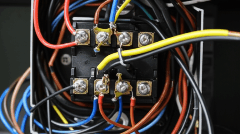
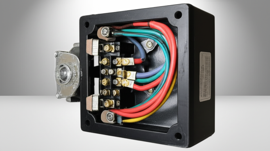
How Do You Wire a Motor to a DOL Starter Step by Step?
A Direct On-Line (DOL) starter wiring job uses a contactor, an overload relay, and a circuit breaker or fuses. The power path uses L1 L2 L3 in to the contactor then to the overload then to the motor.
Components you need:
- Three-Phase Power Supply
- Disconnect Switch
- Circuit Breaker
- Contactor wiring 3 phase motor
- Thermal overload relay 3 phase
- Terminal lugs 3 phase motor and a terminal block
- Control circuit with push button (Start/Stop)
- Grounding Electrode Conductor
Steps:
This is classic 3 phase motor starter wiring used in shops and plants. Use NEMA motor wiring sizes for coils and contact ratings. Mount in an electrical panel. Tie to a busbar if the panel uses a bus. Keep the ladder logic diagram simple.
How Do You Wire a Motor to a VFD the Right Way?
A Variable Frequency Drive (VFD) gives you speed control and smooth starts. It has L1 L2 L3 input a DC bus and U V W output. Some drives say T1 T2 T3. Follow the manual.
Key points:
- Use a shielded motor cable on the output. This helps with harmonic mitigation VFD and reduces EMI. It also helps with shaft grounding for VFDs if you add a ring.
- Use a line reactor or input filter if your line is noisy or the run is long.
- Make a good ground from drive to motor and to the panel ground.
Steps:
This section covers the popular task: how to wire a 3 phase motor to a VFD. You can also use a VFD to do single phase to 3 phase motor wiring for light loads. Check the drive spec first. Some allow single-phase input. Match power supply requirements 3 phase and do not oversize poorly.
What About Advanced Wiring Cases and Special Starters?
You may see these setups in the field.
- Wye-Delta (Star-Delta) starter wiring uses two contactors to start in Star then run in Delta. The star-delta starting method reduces inrush current. It is a reduced voltage starter wiring method.
- A soft start 3 phase motor wiring uses a Soft Starter to ramp voltage and limit current. Good for pumps. It saves starting current (LRA) stress.
- Reversible 3 phase motor wiring swaps any two phases with a reversing contactor. Use interlocks so you cannot run forward and reverse at the same time.
- Some jobs use rotary phase converter wiring or static phase converter wiring. This is for shops with only single phase but they need to run a 3-phase motor. A phase converter can help a small shop run a lathe. A VFD can also do this in many cases.
- Special transformer setups include transformer connection 3 phase and open delta connection wiring or closed delta connection wiring for certain services.
How Do You Test Your Work and Start Up Safely?
Before you press Start you test. Always.
- Do a continuity test 3 phase motor with a multimeter. Make sure no winding is open and no winding ties to the frame.
- Do a Megger test 3 phase motor with a megohmmeter (Megger). Check insulation resistance per the motor insulation class and your company practice.
- Check phase sequence indicators with a phase rotation meter. Make sure the rotation matches the need of the machine. If it spins wrong change any two outgoing phase wires to the motor. That is changing 3 phase motor rotation.
- Verify grounding a 3 phase motor. Confirm the grounding electrode conductor is tight and sized right.
- On first run check ampere meter (clamp meter) readings. Compare to Full load amps (FLA) on the nameplate. Confirm your overload protection 3 phase motor setting.
Listen for troubleshooting motor hum. Watch for troubleshooting motor overheating. Check for vibration analysis motor issues. If the motor bearings growl or the shaft heats up you may have alignment issues or drive harmonics.
What Are Common Wiring Mistakes and How Do You Fix Them?
Problem: People misread diagrams. They guess at leads. They skip grounds.
Agitate: Wrong links fry windings. Loose lugs arc and heat up. Panels trip. Work stops.
Solution: Slow down. Follow the diagram. Torque lugs. Test rotation.
Common issues:
- Incorrect phase sequence. The motor runs backward or not at all. Fix with two-phase swap.
- Loose connections. They cause heat and intermittent trips.
- Improper grounding. That is a safety hazard. It adds electrical noise in VFD wiring specifics.
- Incorrect overload setting. It trips too soon or too late.
- Motor hums but doesn’t start. Check voltage. Check control wiring. Check stuck contactor.
- Motor not starting cases often point to wrong control voltage or a tripped overload relay.
- Overheating issues can come from overloads bad ventilation blocked fans high ambient or long cable runs with high voltage drop calculations 3 phase.
When in doubt use troubleshooting 3 phase motor wiring steps. Check fuses first. Then breakers. Then the coil. Then the control loop. Use your electrical schematics 3 phase motor as your guide.
What Tools and Materials Do You Need?
Bring the right tools and parts. You work faster and safer.
- Test gear: Multimeter, Voltage Meter, Phase Rotation Meter, Ampere Meter (Clamp Meter), Megger.
- Hand tools: Wire strippers, insulated screwdrivers, torque wrench.
- Wiring gear: Electrical tape, heat shrink tubing, cable ties, ferrule (wire end terminal), gland nut/connector, terminal lugs.
- Protection and routing: Conduit (EMT, IMC, RMC, PVC), flexible conduit 3 phase motor, rigid conduit 3 phase motor, cable glands 3 phase motor.
- Panel parts: contactor, overload relay, circuit breaker, disconnect switch, junction box, terminal block.
- Control parts: push buttons, selector switches, control transformer, emergency stop wiring 3 phase devices.
Use the right wire insulation types 3 phase for heat and environment. Use correct wire gauge (AWG, mm²) per ampacity and length.
How Do You Size Wires, Breakers, and Overloads?
You must size parts by the code. In the U.S. use the National Electrical Code (NEC) Article 430. Also follow local rules and IEC standards where they apply.
- Wires. Use wire gauge for 3 phase motor based on Full load amps (FLA). Size conductors for 125% of FLA for continuous duty per code guidance. Use tables like NEC 310.16 and 430.250 for guidance.
- Breakers. Circuit breaker sizing 3 phase uses short circuit protection 3 phase rules in NEC 430.52. This is not the overload protection.
- Overloads. Size per NEC 430.32. Many motors set overloads at 115% of FLA if service factor is 1.15 or more. Others at 125%.
Here is a sample table you can use for planning. Always verify with current code tables and the motor nameplate.
| Item | Example Method | Notes |
|---|---|---|
| Amperage calculation 3 phase motor | Use nameplate FLA | Do not guess from HP if you have the FLA |
| Wire size | 1.25 × FLA then pick AWG from table | Check temp and conduit fill |
| Breaker size | 2.5 × FLA max for inverse time CBs if allowed | Short circuit and ground fault only |
| Overload setting | 1.15 × FLA with SF ≥ 1.15 else 1.25 × FLA | Protects motor windings |
Do voltage drop calculations 3 phase for long runs. Keep drop ideally under 3% for branch circuits. This helps motor efficiency standards goals and keeps torque strong.
How Do You Ground and Route Cables the Right Way?
Ground everything right. Use a grounding electrode conductor sized by code. Bond your metal conduit. Use conduit requirements 3 phase motor that match the site. Pick rigid conduit or flexible conduit based on movement and vibration.
Do good cable routing 3 phase. Keep control wires away from VFD output leads to reduce noise. Use cable glands 3 phase motor to seal enclosures. Use gland nut/connector that fits the cable size. Add heat shrink tubing and ferrules for clean terminations. Use a torque wrench for torque settings for terminals so lugs hold firm.
Maintenance: How Do You Keep the Motor Healthy?
Good care keeps you out of trouble.
- Do preventative maintenance 3 phase checks. Tighten lugs. Clean the box. Check for heat at the lugs. Check megger values over time.
- Keep diagrams in the panel. That is keeping wiring diagrams updated and helps techs later with motor repair wiring and replacing 3 phase motor.
- Check bearings and do light vibration analysis motor. Listen to the fan cooled motor. Clean vents. Watch for dust and oil.
When Should You Call a Pro and Check Codes?
Some work needs a certified electrician. Follow certified electrician guidelines and professional electrical wiring practices. If you are in training follow apprenticeship electrical wiring rules with a mentor. Always meet electrical code compliance for your site. Check NEMA standards and IEC standards. Buy listed gear with UL and CSA marks. Keep your control panel design 3 phase clean and safe.
Why Do Quality Laminations Matter to Motor Life?
Here is a secret many skip. The quality of the stator and rotor steel stacks inside the motor affects heat and loss. Good steel and tight stacks reduce stray loss and buzz. That helps when you run from a VFD since harmonics try to waste energy.
If you build or buy motors or if you repair them you should look at the lamination quality. You can learn more here:
- Strong stator core lamination reduces iron loss and heat.
- Durable rotor core lamination helps torque and lowers noise.
- Consistent motor core laminations support long life and stable motor efficiency standards.
- Clean electrical steel laminations improve performance in motors and transformer coils.
High grade laminations also support shaft grounding for VFDs plans since you manage flux paths better. That helps reduce bearing currents when you use a VFD. Better cores mean cooler motors and fewer troubleshooting motor overheating calls.
References
- National Electrical Code (NEC), NFPA 70, Articles 310 and 430
- NFPA 70E, Standard for Electrical Safety in the Workplace
- OSHA Electrical Safety, Lockout/Tagout
- IEC Standards for rotating machines and wiring
- IEEE 519 Recommended Practice for Harmonic Control
- NEMA MG 1, Motors and Generators
- U.S. Department of Energy, Motor systems basics
- EASA, Best practices for motor repair
Extra Help: Concepts and Learning Links
If you want to review basic ideas try these friendly explainers:
- See how cores shape performance with the motor core laminations guide above.
- Review how stator and rotor work together with a simple explainer.
- Explore a clear take on motor principle and rotating fields.
- Troubleshoot common issues fast with a handy motor problem checklist.
Note: If you need deeper theory look up “stator and rotor” structure and “motor principle” of three-phase fields. It helps you wire with confidence and to read any electrical schematics 3 phase motor that you see.
Quick FAQ
- How do I check motor rotation direction 3 phase without risk?
Jog the motor with the coupling out. Use a phase rotation meter before you land the load. Swap two phases if it is wrong.
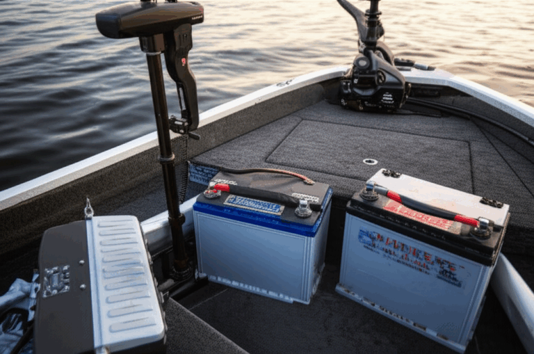
- Can I wire a 3-phase motor at home?
Yes with care. Many homes do not have 3-phase service. You can use a VFD with single-phase input or a rotary phase converter for small loads. This is DIY 3 phase motor wiring (with caution). Follow codes and use a pro if unsure.
- What if the motor hums but will not start?
Check supply voltage. Check control power. Check the overload relay and the contactor. Inspect the terminal block for loose lugs.
- What is power factor correction 3 phase for?
It adds capacitors to offset reactive load. It can lower bills in plants. Do not place PF caps on the load side of a VFD. Put them on the line side as needed.
Data and Best Practices Table
| Category | Data or Tip | Why It Matters |
|---|---|---|
| Motor utilization | Motors use a large share of plant energy | Good wiring protects that investment |
| Common wiring errors | Wrong voltage links wrong phase rotation loose connections | Can cause damage trips and downtime |
| Wire sizing | Size at 125% of FLA then pick AWG from tables | Prevents heat and drop |
| Overcurrent vs overload | Breaker protects from shorts. Overload protects windings | Both are needed |
| VFD wiring specifics | Use shielded cable and good grounding. Use line/load reactors if needed | Reduces harmonics and noise |
| Grounding | Bond all metal. Size grounding electrode conductor right | Safety and noise control |
| Testing | Use continuity test 3 phase motor and Megger test 3 phase motor | Catches faults before you start |
| Documentation | Keep electrical schematics 3 phase motor in the panel | Speeds repair and changes |
| Controls | Add emergency stop wiring 3 phase and clear labels | Keeps people safe |
PAS Woven Into Real Work
- Problem: You face a tangle of wires. The 3 phase motor wiring diagram looks complex.
- Agitate: One wrong link and you risk a blown overload relay or a fried winding. The job stops. Your boss waits.
- Solution: Follow the steps in this guide. Check the motor nameplate. Choose Star or Delta. Land L1 L2 L3 to T1 T2 T3. Test rotation. Set the overload to match FLA. Use a VFD when you need soft starts and speed. Add a soft starter or a Wye-Delta starter when you need to limit inrush on large fans.
Final Notes on Panels and Diagrams
Do smart panel wiring 3 phase motor. Keep control and power separate. Route wires with clean bends. Label every wire. Use control panel design 3 phase best practices and a neat ladder logic diagram. Keep a printed wiring a 3 phase induction motor diagram in the door. Add a note with date and tech name.
If you need transformer connection 3 phase for control power use a control transformer with primary taps that match the line. Ground the secondary when code requires it. Size the fuse for the control loop right.
Summary: Most Important Things to Remember
- Respect power. Use LOTO and PPE every time.
- Read the motor nameplate. Match voltage and FLA.
- Pick the right links for Star or Delta or dual voltage.
- Use a DOL starter or a VFD as the job needs.
- Size wires breakers and overloads by code.
- Ground the motor and the panel well.
- Test with a multimeter, Megger, and a phase rotation meter before a full start.
- Watch for noise heat and vibration. Fix issues fast.
- Keep diagrams up to date. Label everything.
- Choose quality cores and parts. Good laminations help motors run cool and last long.
Bold steps. Clear checks. Safe starts. That is how you wire a 3-phase motor the right way.