How to Safely Wire a VFD to a Compatible Single-Phase Motor (Step-by-Step Guide)
Every design engineer and skilled technician eventually faces the challenge: you need precise speed control, soft-start capabilities, and energy savings, but you’re working with a single-phase motor. The immediate solution that comes to mind is a Variable Frequency Drive (VFD), a powerhouse of motor control. But hooking one up to a single-phase motor isn’t as straightforward as it is with its three-phase cousins. If you’ve ever found yourself staring at a wiring diagram, wondering how to handle the capacitors or which motor types are even compatible, you’re in the right place.
Wiring a VFD to a single-phase motor is an elegant solution to a common engineering problem but it’s a path filled with critical details. Get it right, and you unlock a new level of performance and efficiency. Get it wrong, and you risk damaging the motor, the VFD, or both.
This guide is designed to be your expert consultant. We’ll walk you through the entire process, from understanding the core principles and confirming compatibility to the final wire connections and programming. We’ll demystify the process, explain the “why” behind each step, and empower you to complete the task safely and effectively.
What We’ll Cover
- VFD and Single-Phase Motor Compatibility: The make-or-break first step. We’ll cover which motors work and, more importantly, which ones don’t.
- Essential Tools and Materials: A simple checklist to ensure you have everything you need before you start.
- Pre-Installation Steps: Sizing your VFD and choosing the right location to ensure long-term reliability.
- Step-by-Step VFD Wiring Guide: The core of this article, with detailed instructions for power input, motor preparation, and output connections.
- Initial VFD Setup and Programming: Turning your VFD from a box of electronics into an intelligent motor controller.
- Testing, Commissioning, and Safety Checks: How to safely power up your system for the first time.
- Troubleshooting Common Issues: Your guide to solving problems like motor humming, frequent trips, and overheating.
- Best Practices and Advanced Considerations: Taking your installation from functional to professional with tips on noise filtering and protection.
VFD and Single-Phase Motor Compatibility: What You Need to Know
Before you strip a single wire, the most critical question is: will your motor even work with a VFD? This isn’t a simple yes or no; it depends entirely on the motor’s design. A VFD works by taking incoming AC power, converting it to DC, and then creating a new, synthesized three-phase AC output of a variable frequency. This “trick” is what allows it to control speed. The problem is that most single-phase motors were never designed to be controlled this way.
Compatible Motor Types: The Green Light
For the most part, you have one primary candidate for successful VFD control:
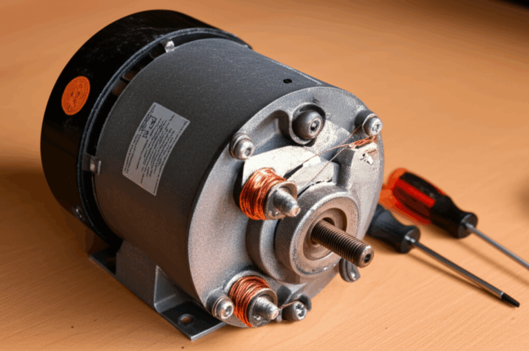
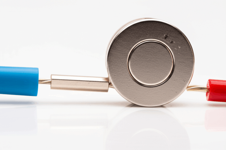
- Permanent Split Capacitor (PSC) Motors: This is the most common and suitable type of single-phase motor for VFD control. A PSC motor uses a run capacitor (and only a run capacitor) to create a phase shift in its auxiliary winding. This design means both the main and auxiliary windings are energized the entire time the motor runs. When you remove the capacitor and connect these two windings to separate outputs of a VFD, the drive can take over the job of creating that phase-shifted signal, effectively turning the PSC motor into a two-phase motor that it can control beautifully.
Some manufacturers also produce specific single-phase induction motors that are explicitly rated for VFD (or “inverter-duty”) use. These are less common but are a guaranteed safe bet if you can find one that matches your application.
Incompatible Motor Types: The Red Light (And Why)
Attempting to wire a VFD to the following motor types will almost certainly lead to failure. Here’s why:
- Capacitor-Start Motors (and Capacitor-Start, Capacitor-Run): The name says it all. These motors use a high-capacitance start capacitor and a centrifugal switch. When the motor nears its full speed, this mechanical switch physically disconnects the starting capacitor and winding from the circuit. A VFD controls speed by varying the frequency, meaning the motor might often run at speeds too low for the centrifugal switch to open. This leaves the start winding engaged, causing it to quickly overheat and burn out. It’s a fundamental incompatibility that can’t be easily bypassed.
- Split-Phase Motors: Similar to capacitor-start motors, these use a starting winding and a centrifugal switch but without the capacitor. The same problem applies: running at variable speeds means the switch won’t operate correctly, leading to a fried start winding.
- Shaded-Pole Motors: These are simple, low-torque motors often used in small fans. Their design relies on a completely different principle for starting and isn’t compatible with the way a VFD manipulates frequency and voltage.
- Universal Motors: Found in power tools and appliances, these motors can run on AC or DC power and use brushes. They are designed for high-speed operation and their speed is controlled by varying voltage not frequency making them unsuitable for VFD control.
VFD Type Selection: The Heart of the System
You must use a VFD that is specifically designed for a single-phase input. These drives are built to accept the Line and Neutral/Line 2 from a standard residential or light commercial supply (e.g., 120V or 230V single-phase).
However, the crucial part is the output. Nearly all VFDs, including those with single-phase input, produce a three-phase output (U, V, W or T1, T2, T3). Don’t let this confuse you! You won’t be using all three outputs in the traditional sense. Instead, you’ll typically use two of the three outputs to power the main and auxiliary windings of your compatible PSC motor.
Interpreting the Motor Nameplate
Before you buy a VFD, look at your motor’s nameplate. You need to find:
- Voltage (V): The VFD’s input voltage must match your supply, and its output voltage range must match the motor.
- Full Load Amps (FLA): This is the most important number. Your VFD must have a current rating (Amps) equal to or, ideally, slightly higher than the motor’s FLA.
- Horsepower (HP) or Kilowatts (kW): A good secondary check. Match the VFD’s HP/kW rating to the motor. When in doubt, always size based on Amps.
- Frequency (Hz): Usually 50Hz or 60Hz. This will be your base frequency setting in the VFD.
Finally, safety is paramount. Before starting any work, implement Lockout/Tagout (LOTO) procedures to ensure the circuit is de-energized and cannot be accidentally turned back on.
Essential Tools and Materials
Having the right gear makes the job smoother and safer. Here’s a quick checklist:
Tools:
- Insulated Screwdrivers (Phillips and flat-head)
- Wire Strippers/Cutters
- Wire Crimpers (for terminals, if needed)
- Digital Multimeter (for verifying power is off and checking windings)
- Nut Drivers or a Socket Set
- Drill and bits (for mounting the VFD)
Materials:
- The correctly sized, single-phase input VFD
- Your compatible PSC motor
- Appropriate gauge wire for both the power input and motor output (check the VFD manual and local electrical codes)
- Conduit and fittings (if required by code)
- A suitable disconnect switch or circuit breaker for the VFD input
- Ring or fork terminals for clean wire connections
- Grounding screws or lugs
Pre-Installation Steps
A little planning goes a long way.
1. Sizing the VFD Correctly
As mentioned, you must size the VFD to your motor. The golden rule is to use the motor’s Full Load Amps (FLA). For single-phase motors, it’s also common practice to oversize the VFD. For example, if you have a 1 HP single-phase motor, you might use a VFD rated for a 2 HP three-phase motor. This de-rating gives the VFD’s components plenty of headroom to handle the unbalanced load presented by a single-phase motor. Always consult the VFD manufacturer’s documentation for guidance on single-phase motor applications.
2. Choosing the Right Mounting Location
VFDs are powerful electronics and they generate heat. They need to breathe.
- Ventilation: Mount the VFD in a clean, dry location with adequate airflow. Pay attention to the clearance requirements specified in the manual (usually a few inches on all sides).
- Enclosure: If the VFD is in a dusty, damp, or harsh environment, it must be installed in a suitable NEMA-rated enclosure.
- Vibration: Avoid mounting the VFD on a surface with excessive vibration.
- Accessibility: Ensure you can easily access the VFD for wiring and programming.
3. Running Your Cables
Plan your wire runs. It’s best practice to run the motor output wires in a separate conduit from the power input wires to minimize electrical noise (EMI/RFI). If you must cross them, do so at a 90-degree angle. For longer runs or in electrically noisy environments, using shielded VFD cable for the motor connection is highly recommended.
Step-by-Step VFD Wiring to a Compatible Single-Phase Motor
Here we are—the main event. Follow these steps carefully. Remember: Power must be turned OFF and verified with a multimeter before you begin.
Step 1: Disconnect and Verify Power
Turn off the circuit breaker feeding the location where you’ll be wiring the VFD. Use your multimeter to test the incoming power lines (L1 to L2/N, L1 to Ground, L2/N to Ground) to ensure they are completely de-energized. This is a non-negotiable safety step.
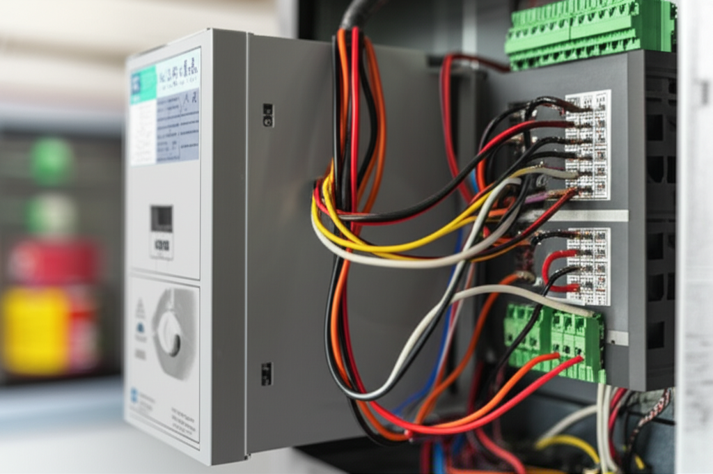
Step 2: Wiring Input Power to the VFD
This is the power coming from your main electrical panel.
Step 3: Preparing the Single-Phase Motor for VFD Control (The Critical Part)
This is where you modify the PSC motor to accept the VFD’s control signals. You are essentially performing surgery to remove the components the VFD will now replace.
Step 4: Wiring Motor Output from the VFD
Now, you’ll connect the prepared motor to the VFD’s three-phase output terminals.
Wait, why are we connecting a single-phase motor to a three-phase output?
Think of it this way: The VFD’s output U, V, and W are three distinct, phase-shifted AC signals. By connecting the main and auxiliary windings to two of these signals (e.g., U and V), the VFD creates a precise electrical 90-degree phase shift between them—exactly what the original capacitor did, but now it’s electronically controlled and variable. This gives you perfect control over the motor’s operation.
Step 5: Wiring Control Inputs (Optional)
Most VFDs can be controlled by external switches or a potentiometer for variable speed. This is where you can add user controls.
- Potentiometer for Speed: Wire a potentiometer (typically 5k or 10k Ohm) to the VFD’s analog inputs (e.g., +10V, AIN, and GND) to allow for manual speed adjustment with a knob.
- Start/Stop Buttons: Wire momentary push buttons to the digital inputs to create an external start, stop, or direction control panel.
- Emergency Stop (E-Stop): Wire a normally-closed E-Stop button in series with your control circuit for safety.
Always refer to your specific VFD’s manual for the exact terminal designations for these control inputs.
Initial VFD Setup and Programming Parameters
With the wiring complete, it’s time to program the drive. Don’t skip this! Using default settings can lead to poor performance or motor damage.
- Motor Voltage (e.g., 230V)
- Motor Full Load Amps (FLA)
- Base Frequency (e.g., 60 Hz)
- Motor Horsepower or kW
- Minimum and Maximum Frequency (e.g., 5 Hz to 60 Hz)
Testing, Commissioning, and Safety Checks
Now for the moment of truth.
Troubleshooting Common Issues
Even with careful installation, you might run into a snag. Here are a few common problems:
- Motor Hums But Doesn’t Start: This often points to incorrect wiring of the main and auxiliary windings or a VFD parameter setting that’s limiting the starting torque. Double-check your connections and the V/Hz boost settings.
- VFD Trips on Overcurrent/Overload: This can be caused by acceleration ramps that are too fast, a mechanical load that is binding, or incorrect motor amp settings in the VFD. Try increasing the accel time first. Any significant motor problem like a bearing failure can also cause an overload.
- Motor Overheating: Running a standard motor at very low speeds for extended periods can cause it to overheat because its built-in cooling fan becomes less effective. Ensure the motor is not overloaded and consider using a separate, constantly powered cooling fan if low-speed operation is required.
- VFD Trips on Ground Fault: This indicates a short circuit between a motor winding and the motor’s frame. It’s a serious safety issue. Disconnect the motor and use a megohmmeter to test the motor windings for insulation breakdown. The issue could lie within the motor’s internal stator and rotor assembly.
Best Practices and Advanced Considerations
To make your installation robust and reliable, consider these professional touches:
- EMI/RFI Filtering: VFDs can generate electrical noise that interferes with other electronics. Using shielded VFD cable between the drive and the motor is the best way to contain this noise. Proper grounding of the shield at both ends is essential.
- Line and Load Reactors: A line reactor installed on the input side of the VFD can help reduce harmonic distortion and protect the drive from power line fluctuations. A load reactor, installed on the output, can protect the motor’s insulation from the VFD’s high-frequency voltage pulses, especially with long cable runs.
- Proper Ventilation: For a VFD in an enclosure, ensure there is adequate ventilation, or even a cooling fan, to dissipate heat. The leading cause of premature VFD failure is overheating.
Conclusion: Empowered and In Control
Wiring a VFD to a single-phase motor is a powerful upgrade that puts you in complete control of your application. While it requires more care and knowledge than a standard three-phase installation, the benefits in performance, energy efficiency, and mechanical longevity are undeniable.
By following this guide, you’ve learned to navigate the critical challenges of this task. Let’s recap the most important takeaways:
- Compatibility is King: The project’s success hinges on starting with a compatible motor, most often a Permanent Split Capacitor (PSC) type.
- Preparation is Crucial: Correctly identifying windings and, most importantly, removing the run capacitor are non-negotiable steps.
- Programming Matters: The VFD’s parameters must be set to match the motor’s nameplate data to ensure safe and optimal performance.
- Safety First, Always: From LOTO procedures to proper grounding, never compromise on safety.
You now have the knowledge to approach this project not with uncertainty, but with the confidence of an informed engineer. You understand the “why” behind the “how,” empowering you to make smart decisions, troubleshoot effectively, and unlock the full potential of your single-phase motor. If at any point you feel unsure, don’t hesitate to consult your VFD’s documentation or a qualified electrical professional.