How to Tell If Your Motor Is Seized — And How Lamination Choices Help Prevent It
Every engineer has faced the gut-check moment. A critical motor or engine refuses to turn. Operations stall. Fingers point. You need to know if the motor is seized, why it happened, and what you can do next. If you also own the upstream decision on materials and manufacturing for the motor’s stator and rotor laminations, you already know those choices ripple through efficiency, temperature rise, reliability, and yes, “lock-up” risk.
You’re in the right place. This guide helps you diagnose a locked motor quickly, then connects the dots to lamination design, material selection, and manufacturing routes that prevent seizure and improve long-term performance. We’ll keep it practical, engineering-first, and balanced.
In This Article
- What “Seized” Really Means and Why It Matters
- Fast Field Checks: How to Tell if a Motor Is Seized
- The Engineering Fundamentals: Why Motors Lock Up
- Material Considerations for Laminations
- Manufacturing and Assembly Choices That Affect Reliability
- “Which Application Is This For?”—Best-Fit Guidance
- Distinguishing a Seized Engine From Other Problems (ICE vs Electric)
- Preventing Seizure: Design Rules and Maintenance Practices
- Your Engineering Takeaway and Next Steps
What “Seized” Really Means and Why It Matters
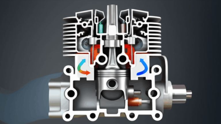
Let’s define the problem in clear terms. A motor is “seized” when the rotor cannot rotate relative to the stator under normal operating torque because a mechanical or thermal condition has created an interference, a weld-like bond, or a catastrophic internal failure. In internal combustion engines, seizure usually means the crankshaft will not turn because pistons locked in the cylinders or bearings melted and galled under oil starvation or severe overheating. In electric motors, seizure more often traces to bearings, rotor-stator rubbing from thermal growth or misalignment, or a foreign object. Sometimes a locked gearbox or driven load makes the motor look seized when it isn’t.
Why it matters is simple. Seizure leads to downtime, safety risks, and high costs. Replacement and repair decisions get expensive fast. The faster you diagnose the root cause, the better your odds of salvaging inventory and avoiding repeat failures. For product designers and procurement managers, a seized field unit signals upstream risks: lamination losses that run the motor hotter than modeled, incorrect material grades for frequency, assembly distortions, or an insulation system that broke down.
Fast Field Checks: How to Tell if a Motor Is Seized
You need a decision tree that separates seized from “won’t start” or “jammed load.” Start with basic, non-destructive steps.
- Electric motors: power isolated
- Free-rotation test: With power disconnected and locked out, try to rotate the shaft by hand or with a strap wrench. It should spin smoothly with consistent drag. If it binds or will not move, the motor may be seized.
- Listen and feel: Gritty feel or scraping sound suggests bearing damage or rotor-stator rub. A thud followed by zero movement points to a hard mechanical lock like a foreign object or deformed lamination edge contacting the rotor.
- Endplay and runout: Push-pull the shaft axially and check radial play. Excessive endplay or bent shaft creates rotor-stator contact during operation.
- Decouple the load: Remove the coupling or belt. If the motor spins freely without the load, the driven machine is the culprit.
- Compressors and industrial drives
- Try a low-torque jog at safe voltage under supervision. If the motor hums and the shaft does not rotate, do not keep trying. You risk winding damage and further mechanical distortion.
- Inspect for heat history. Discolored housings, burnt odor, or darkened grease indicate overheating.
- Internal combustion engines (fast checks to separate from battery and starter issues)
- Car won’t start no crank: Check the battery first. A dead battery can mimic a seized engine. Voltage under 12.2 V at rest is suspect. Jump start or charge and try again.
- Starter motor clicking only: A click with no crank often means low battery or high resistance at connections. A solid “clunk” with locked crank after a healthy starter engagement suggests the engine may be seized.
- Manual crank test: Put a wrench on the crankshaft pulley bolt and try to turn it clockwise. No movement despite reasonable force indicates a likely seizure.
- Pull spark plugs to check for hydro-lock. Coolant or water in cylinders prevents rotation. If liquid sprays out when you turn the engine slowly by hand, you had hydrostatic lock.
If you confirm a true mechanical lock inside the electric motor or the engine, stop. You need a structured teardown or a professional assessment. Continued attempts to power through a lock almost always make things worse.
The Engineering Fundamentals: Why Motors Lock Up
Now the “why.” Electric machines lock when thermal, mechanical, or magnetic factors push the system past its margin. Several common physics threads tie back to lamination design and material choice.
- Eddy current and hysteresis loss drive heat
- Eddy currents are like unwanted whirlpools in a river. A changing magnetic field induces circulating currents in a conductive core that waste energy as heat. Thinner laminations with good interlaminar insulation break up those whirlpools.
- Hysteresis loss is the energy required to flip magnetic domains each AC cycle. Materials with lower coercivity reduce this loss. In both cases, lower core loss means lower temperature rise at a given flux density.
- The practical consequence: if your lamination thickness is too high for the operating frequency, or if the insulation coating is inconsistent, core losses climb. Heat rises. Bearings run hotter. Clearances shrink. Eventually the rotor can kiss the stator.
- Thermal growth and stack distortion
- All materials expand with temperature. Rotor OD grows and stator ID shrinks relative to each other whenever heat builds. Poor control on stack flatness, burr height, and alignment turns normal thermal growth into rub.
- Welded, bonded, or interlocked stacks can distort if process parameters are off. Distorted stacks tend to “egg-shape” bores which reduces minimum air-gap and increases rub risk.
- Mechanical tolerances and burrs
- Burrs on stator tooth tips or in the rotor slot land act like tiny knives. If they protrude into the air-gap or loosen during operation, they can initiate rub or cut into insulation.
- Tight tolerances on rotor-stator concentricity and shaft runout are not “nice to have.” They are the line between whisper-quiet and noisy rub that cascades into lock-up.
- Insulation breakdown and partial discharge
- Poor or damaged interlaminar insulation lets laminations short together. That increases eddy currents and heat. Combined with varnish failures and winding hot spots, the system can spiral toward seizure.
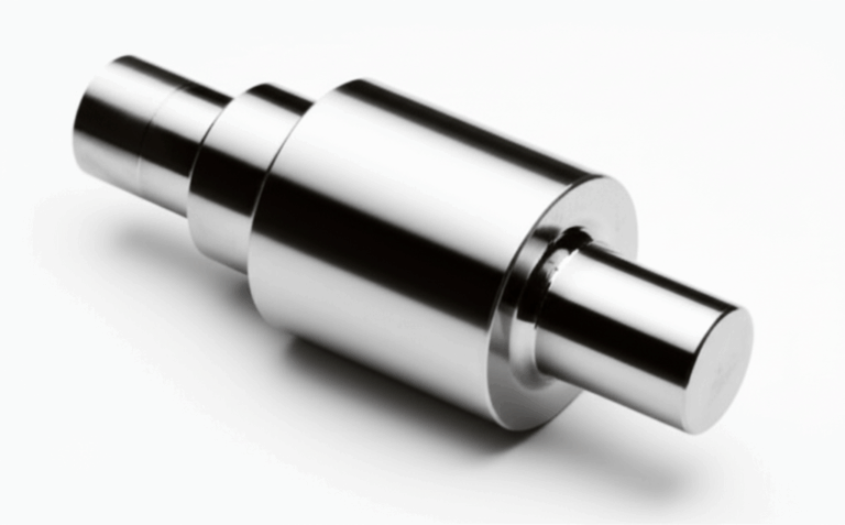
- Bearings and lubrication
- In electric motors, bearings fail far more often than laminations. Heat accelerates grease breakdown. Shock loads dent races. Once the balls skid instead of roll, friction spikes. The motor can lock solid in minutes.
For internal combustion engines the physics looks different but the pattern rhymes. Oil starvation increases friction and heat. Pistons scuff. Bearings seize on the crankshaft. Severe overheating warps heads and tightens piston-to-wall clearances until the crankshaft will not turn. Hydro-lock stops pistons dead because water does not compress. Different components. Same story. Heat and interference lead to seizure.
Material Considerations for Laminations
Choosing the right electrical steel and thickness is your first lever against heat-driven failure. Focus on operating frequency, flux density, temperature rise, and manufacturability.
- Non-oriented silicon steel (NOES)
- Typical grades: 50A800, M19 class analogs, and similar per supplier nomenclature.
- Best for: General-purpose induction motors and generators up to several hundred hertz.
- Pros: Balanced performance independent of direction, widely available, cost effective.
- Cons: Higher core loss than premium high-silicon NOES or cobalt alloys at high frequency.
- Grain-oriented silicon steel (GOES)
- Best for: Transformers where flux aligns with the rolling direction.
- Pros: Very low loss along the rolling direction.
- Cons: Poor performance in off-axis applications. Not ideal for rotating machines with varying field direction.
- High-silicon NOES (3.0–3.5% Si)
- Best for: Higher efficiency induction motors and synchronous machines where lower core loss is critical.
- Pros: Lower hysteresis and eddy losses than commodity grades.
- Cons: Brittle material that can challenge tight punch features and complex webs.
- Cobalt-iron alloys
- Best for: High power density and high-frequency applications such as aerospace, high-speed spindles, or specialized BLDC motors.
- Pros: Very high saturation flux density which allows higher B without early saturation.
- Cons: Expensive, harder to cut, and sensitive to process heat.
- Nickel-iron alloys
- Best for: High permeability applications and some specialty sensors or low-loss cores at modest flux densities.
- Pros: Excellent permeability, reduced loss in some regimes.
- Cons: Cost and supply chain considerations.
- Lamination thickness
- Rule of thumb: As frequency goes up, thickness goes down. Eddy current loss scales roughly with the square of lamination thickness and frequency at a given flux swing.
- Typical choices: 0.50 mm for 50/60 Hz general purpose, 0.35 mm for higher efficiency at industrial frequencies, 0.27 mm and below for 400 Hz or high-frequency BLDC inverters. Ultra-thin foils for very high frequency come with cost and manufacturing penalties.
- Interlaminar insulation coating
- Function: Provides electrical isolation between sheets to suppress eddy currents while resisting heat and mechanical stress.
- Types: Inorganic phosphate coatings, organic insulating films, and hybrid coatings with specific Class ratings.
- Selection factors: Temperature rating, punchability, weldability, adhesion, and electrical resistivity. Higher resistivity usually lowers eddy losses but coatings must survive stamping and stacking without flaking.
Standards and data integrity matter. Use reputable MTP data per IEC 60404 methodologies for loss and permeability. If you source to ASTM specifications like ASTM A677 for non-oriented electrical steel, align your supplier’s certification with your design intent and test method.
For a concise overview of lamination families and where they fit, this primer on electrical steel laminations provides a helpful starting point.
Manufacturing and Assembly Choices That Affect Reliability
Material sets the ceiling. Manufacturing determines how close you get.
- Cutting process: stamping, laser, or EDM
- Stamping
- Best for: High volume with repeatable geometry and lowest cost per part once tooling is amortized.
- Pros: Tight feature control when tools are maintained, low part cost, high throughput.
- Cons: Tool wear raises burr height and can stress the steel. Thin gauges and high-silicon grades need careful clearance and lube control. Distortion risk if die set or feeds are out of tune.
- Laser cutting
- Best for: Prototyping, low-volume builds, complex geometries, or frequent design changes.
- Pros: No hard tooling cost, fast iteration, excellent dimensional flexibility.
- Cons: Heat-affected zone can increase loss and degrade magnetic properties unless post-annealed. Edge quality depends on parameters and assist gases.
- Wire EDM
- Best for: Highest precision and minimal mechanical stress on the sheet.
- Pros: Superb edge quality and minimal burr. Very consistent slot geometry.
- Cons: Slow and costly for volume. Usually reserved for critical prototypes or specialty parts.
- Burr control and edge quality
- Keep burr height well below the insulation thickness and far below the air-gap margin. As a rule, target burr height under 10% of lamination thickness for production. Lower is better near air-gap features.
- Measure often. Burr growth is not linear with tool wear. Catch it before it snowballs.
- Stacking methods: interlocking, welding, bonding, or riveting
- Mechanical interlocking
- Works like LEGO bricks. Tabs and slots snap and hold laminations without adhesives or weld heat.
- Pros: Fast, no chemicals, avoids weld heat that harms magnetic properties.
- Cons: Local deformation around tabs can create stack flatness issues if not controlled.
- Welding
- Pros: Strong, reliable, familiar. Good for certain rotor stacks.
- Cons: Heat can increase core loss near the weld and warp stacks. Use minimal weld energy and consider post-process anneal if material allows.
- Adhesive or resin bonding
- Pros: Uniform stress distribution and good damping. Can reduce acoustic noise. No weld heat.
- Cons: Process control matters. Cure schedules, adhesive selection, and cleanliness drive success.
- Riveting
- Pros: Simple and sturdy for small stacks or specific legacy designs.
- Cons: Adds mass and potential imbalance if not symmetrical. Holes reduce net iron.
- Stress relief annealing
- When cutting introduces significant mechanical or thermal stress, proper annealing restores magnetic properties and lowers core loss. Follow the steel supplier’s recommended cycle. Control atmosphere, ramp rates, and soak times. Bad annealing can be worse than none.
- Air-gap control and concentricity
- The air-gap is the heartbeat of a rotating machine. Small errors in stack alignment, bore roundness, or shaft runout raise forces and noise. In worst cases they close the gap at one pole and trigger rub. Use stack gauges, bore gauges, and dynamic runout checks at line rate.
- Surface insulation and varnish
- Good impregnation supports wire vibration damping and heat transfer out of the winding. It also helps hold the lamination stack in dimensional shape. Poor varnish coverage raises local hot spots and noise which nibbles away at bearing life.
You can see how closely this ties to the stator and rotor cores. If you want a deeper view of how these pieces fit, review the fundamentals of the stator core lamination and complementary rotor core lamination options because these two components carry the bulk of the risk and reward in a rotating machine.
“Which Application Is This For?” — Best-Fit Guidance
Match your choices to how the machine lives.
- General-purpose industrial induction motors
- Typical duty: 50/60 Hz mains, variable speed drives up to a few hundred hertz.
- Material: NOES in the 0.35–0.50 mm range with robust, punchable coatings.
- Manufacturing: Progressive die stamping with strict burr control. Interlock or bonding for stators. Selective welds for rotors with controlled energy input.
- Why it works: You get balanced performance and lower cost. Keep core losses down so the frame temperature stays well within bearing grease class. Seizure risk drops because thermal growth stays in check.
- High-efficiency IE3/IE4 motors and premium pump drives
- Duty: Elevated efficiency class with variable frequency drives common.
- Material: High-grade NOES with lower loss at design flux and sub-0.35 mm thickness in many frames.
- Process: Tighter tool maintenance, more frequent deburr checks, and consideration of bonding to minimize mechanical stress.
- Watch-out: Frequency extends into mid-hundreds of hertz which amplifies eddy loss in thicker sheets. Design air-gap for worst-case thermal rise plus runout.
- BLDC and PMSM for e-mobility and robotics
- Duty: High-frequency PWM excitation, high torque density, and dynamic load cycles.
- Material: Very low thickness NOES or cobalt-iron for extreme power density when budget allows.
- Process: Laser or fine blanking for complex tooth shapes, then stress relief anneal if required by the grade. Adhesive bonding can damp vibration and improve NVH.
- Details: Balance electromagnetic performance with demagnetization risk in magnets. Keep lamination edges pristine near magnets to avoid insulation damage.
- If you’re designing in this space, review example options for a BLDC stator core to benchmark slot and tooth strategies.
- High-speed spindles and aerospace
- Duty: Very high rpm with high frequency magnetic cycles and tight envelopes.
- Material: Cobalt-iron or premium NOES with sub-0.27 mm thickness.
- Process: EDM or laser cut with post-anneal. Precision balancing and tight runout control. Adhesive bonding favored for uniformity.
- Tolerance discipline: Every micron matters. The air-gap margin must include thermal growth at top speed.
- Transformers and static magnetic components
- Duty: Magnetically oriented loads with minimal mechanical rotation concerns.
- Material: GOES for cores with aligned flux paths. NOES for chokes or multi-direction fields.
- Why mention it here: The same lamination logic governs temperature rise and magnetic performance that determines how hot your enclosure runs which indirectly affects adjacent rotating equipment.
Distinguishing a Seized Engine From Other Problems (ICE vs Electric)
The search intent behind “how to tell if motor is seized” often comes from ICE users. Here’s a compact guide to separate a true engine lock from common no-start issues alongside parallel electric motor cues. Use it to triage calls from the field.
- Dead battery vs seized engine
- ICE: Dim lights, slow cranking, or rapid clicking point to a weak battery or bad connections. A healthy starter engaging hard then stopping points toward seizure.
- Electric motor: Low DC bus voltage on a VFD or blown fuses will not rotate a healthy motor. Always decouple the load and test free rotation before blaming the motor.
- Starter motor vs engine
- ICE: A starter that spins fast with a whir but no engine rotation suggests a bad bendix or flywheel teeth rather than seizure. Grinding noise during start can be starter alignment not a locked crank.
- Electric motor: A humming motor that will not rotate under power with high input current can be a jammed rotor or single-phasing in a three-phase system. Do not keep energizing. You risk winding damage.
- Fuel system issues vs seized
- ICE: If the engine cranks but will not start, suspect fuel or ignition. That is not seizure. Look for spark, fuel pressure, or DTCs from the ECU.
- Electric motor: If the motor rotates freely by hand but trips protection when starting under load, check the driven machine for mechanical drag or misalignment. Confirm supply balance and VFD parameters.
- Hydro-lock, overheating, and oil starvation (ICE only)
- Hydro-locked engine: Pull plugs and try the manual crank test. Water or coolant in the cylinders will block rotation. If liquid sprays out, you found your issue.
- Overheating: A sweet coolant smell, steam, and a high temperature light often precede a lock. Warped parts can bind. Do not restart until inspected.
- Oil starvation: Low oil pressure warnings followed by knocking sounds and a sudden stop suggest spun bearings or welded journals. That is classic seizure.
These distinctions save time and safety headaches. They also keep you from mislabeling a simple electrical issue as catastrophic internal damage.
Preventing Seizure: Design Rules and Maintenance Practices
You can cut seizure risk dramatically with a handful of design and process disciplines. Let’s split prevention into “design and manufacturing” and “operations and maintenance.”
Design and manufacturing
- Choose lamination thickness for frequency. Drop thickness as frequency rises because eddy loss rises fast with both frequency and thickness. That reduces core temperatures which protects bearings and air-gap margins.
- Select the right coating. Use insulation with adequate temperature class and punchability for your cutting route. Coating must resist flaking or chemical attack during impregnation.
- Control burrs. Set burr limits by zone. Near the air-gap keep burrs negligible. Audit tools and cutting parameters. Deburr as needed with minimal damage to coating.
- Align stacks precisely. Use fixtures that control parallelism and concentricity. Measure bore roundness and OD straightness. Consider bonding to stabilize stacks when NVH or rub risk dominates.
- Balance stress and heat in joining. If you weld, minimize energy and localize heat. If you interlock, balance tab placement to avoid egg-shaped distortion. If you bond, validate cure schedules and environmental stability.
- Verify with data. Test losses per IEC 60404 methods. Correlate stack temperature under load to your thermal model. Iterate before scale-up.
Operations and maintenance
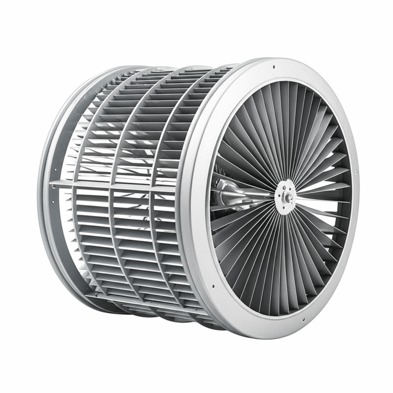
- Respect air-flow. Cooling blockages or fan issues raise stator and rotor temperature which cuts your clearance margin.
- Watch bearings like a hawk. Temperature, vibration, and lubrication schedules matter. Hot bearings fail early and fail hard.
- Keep the load honest. Misaligned couplings and over-tensioned belts pull shafts off center which shrinks the air-gap on one side. That invites rub during transients.
- Monitor with sensors. Add RTDs in end windings and a bearing temp sensor if the stakes are high. The cost is low compared to a seized line.
- Train restart discipline. If a unit trips on overcurrent or overtemp, investigate. Do not keep hitting start. That is how minor rubs turn into seized rotors.
If you need a concise overview of how lamination decisions cascade into motor performance, this summary of motor core laminations helps teams align on requirements early.
Your Engineering Takeaway and Next Steps
Here are the key points to remember when you need to diagnose a seized motor and prevent future cases through better lamination decisions.
- Diagnose first, force never:
- Decouple the load and test free rotation by hand for electric motors.
- For ICE, check the battery and starter first. Use a manual crank test at the crankshaft pulley to confirm a true lock.
- Heat is the common enemy:
- In electric motors, excessive core loss, poor cooling, and bearing distress lead to rub and lock-up.
- In ICE, oil starvation and overheating weld parts together or warp them into interference.
- Lamination choices matter more than you think:
- Select thickness and steel grade for your frequency and flux density.
- Apply robust interlaminar insulation that survives your cutting and stacking processes.
- Manufacturing is where reliability is won:
- Control burrs rigorously. Keep stacks round and flat. Choose joining methods that do not introduce distortion or excessive heat.
- Application fit prevents hard compromises:
- Commodity NOES with 0.35–0.50 mm thickness serves most industrial motors well.
- High-frequency or high-power-density designs benefit from thinner gauges or premium alloys despite higher cost.
- Maintenance closes the loop:
- Bearings, alignment, and airflow keep temperature under control which keeps clearances safe.
If your team is scoping a new motor or troubleshooting temperature headroom and rub risk in a current design, schedule a technical review with your lamination supplier. Come ready with frequency, flux targets, thermal constraints, and manufacturing volume. Ask for loss data according to IEC 60404 methods and discuss stack joining options relative to your NVH goals. For a quick refresher on the two halves of your magnetic circuit, skim the pages on stator core lamination and rotor core lamination then align your tolerances with real-world process capability.
You want higher efficiency, cooler operation, and longer service life. The right laminations get you there. The right processes keep you there. When a motor refuses to turn, use the checks above to find the truth fast then bake prevention into your next design.
— Engineering Team
Notes and references
- Magnetic property measurement methods are defined in the IEC 60404 series. Use these to compare supplier data apples-to-apples.
- ASTM and similar standards cover the chemistry and processing of electrical steels such as ASTM A677 for non-oriented grades. Always confirm final product properties with your supplier’s certified data.