How to Test a Blower Motor Resistor: A Step-by-Step DIY Diagnostic Guide
Table of Contents
- Understanding Your Blower Motor Resistor: What It Does and Why It Fails
- What is a blower motor resistor
- Common symptoms of a bad resistor
- Why resistors fail
- Safety First: Precautions Before You Begin
- Disconnecting the battery
- Working with electrical systems
- Required tools and equipment
- Locating Your Blower Motor Resistor
- General locations
- Tips for specific vehicles
- Step-by-Step Guide: Testing the Blower Motor Resistor with a Multimeter
- Step 1: Visual inspection
- Step 2: Disconnect the resistor
- Step 3: Test for continuity
- Step 4: Test resistance values and variable modules
- Step 5: Test for power and ground at the connector
- Step 6: Reinstall and test
- Interpreting Your Test Results: Is Your Resistor Bad
- Clear signs it failed
- What to check if it tests good
- Replacing a Faulty Blower Motor Resistor
- Why replacing it matters
- OEM vs aftermarket considerations
- Frequently Asked Questions (FAQs)
- Conclusion
Understanding Your Blower Motor Resistor: What It Does and Why It Fails
I have chased more HVAC fan issues than I can count. The pattern rarely changes. The fan only works on high. Or the fan works on two speeds then quits. Sometimes there is no airflow from vents at all. Nine times out of ten I end up at the blower motor resistor or the blower control module on newer cars.
What is a blower motor resistor
Your vehicle’s HVAC system uses a Blower Motor to push air across the heater core or the AC evaporator. The fan speed switch or climate control module sends a command then the Blower Motor Resistor (or control module) limits voltage or current to set the speed. On older systems the resistor is literally a set of resistive coils or a ceramic resistor pack. On many newer systems a solid-state module handles speed with Pulse Width Modulation using a MOSFET or similar Semiconductor Device.
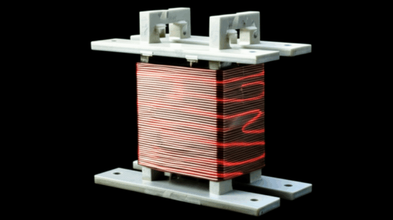
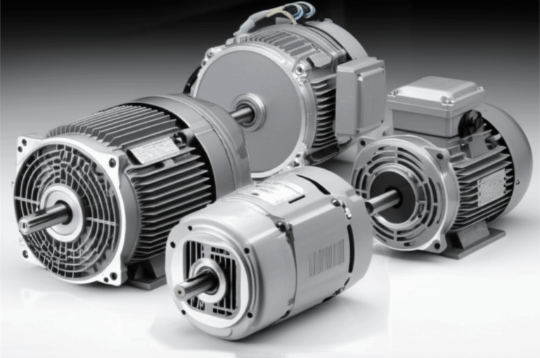
A quick aside for context. The blower motor is a simple electric motor with a stator and a rotor. If you want to visualize how any motor works at its core you might like this primer on the motor principle. For a quick refresher on the motor’s anatomy see stator and rotor. The laminations inside a motor matter to reduce eddy current losses and heat. If you are curious about the materials behind that design you can peek at stator core lamination and rotor core lamination. You do not need those to test your resistor yet I find a little background helps the whole picture click.
Common symptoms of a bad resistor
Here is what I see most often when the resistor or control module fails:
- AC fan only works on high. Or only works on one speed.
- Some speeds work then cut out intermittently. Wiggle the connector and it comes back.
- No fan on low or medium yet high screams like a jet.
- Heater fan not working on any setting. Sometimes this is the resistor. Sometimes it is power supply or the blower motor itself.
- Burnt plastic smell near the passenger footwell. You might spot melting on the Electrical Connector or the resistor pack.
You can also check the classics:
- Blower motor speed control behaves erratically.
- HVAC fan not working after a rainstorm or after someone replaced the cabin air filter.
- Dashboard controls not working on the fan side while lights still come on.
Why resistors fail
Resistors live hard lives. They run hot by design and heat kills components. Here is what usually takes them out:
- Overheating from excessive current draw. A worn or stiff Blower Motor draws more amps which cooks the resistor or the Thermal Fuse inside it.
- Poor airflow across the resistor block. Most resistor packs sit in the airflow path. Leaves or debris reduce cooling which overheats the Ceramic Resistor.
- Age and vibration. Solder joints crack. Resistor coils fatigue. The thermal cut-off weakens.
- Corroded or loose Wiring Harness connections. Corrosion raises resistance at the connector which generates more heat and melts stuff.
- Short circuit or open circuit events caused by rubbing wires or water intrusion.
- On PWM modules the MOSFET overheats or fails due to voltage spikes. A bad ground makes that worse.
I learned a painful but useful lesson years ago on a compact sedan. The fan only worked on high. The resistor looked cooked. I replaced it then sent the car out. It came back two weeks later with a melted connector. The root cause was a blower motor that pulled too much current. I now always evaluate motor current draw before I call a resistor job done.
Safety First: Precautions Before You Begin
I treat automotive electrical troubleshooting with respect. You should too. The steps are simple and safe if you slow down.
Disconnecting the battery
- Turn the Ignition Key off.
- Disconnect the negative Battery cable before unplugging the resistor or motor. This avoids shorts and protects your Multimeter. You will reconnect it when you need to measure live Voltage.
Working with electrical systems
- Use eye protection. Rust flakes and foam bits love to fall out from under the dash.
- Never probe connectors with oversized tools. You can spread terminals which creates intermittent problems later.
- Avoid back-probing with large pins unless you have the correct probe kit. I prefer thin back-probe needles or a Test Light with a fine tip.
- Keep Automotive Electrical Safety in mind. Support the glove box door if you drop it. Secure trim panels.
Required tools and equipment
You do not need fancy gear. I test most blower motor resistors with:
- Digital Multimeter. It covers Ohmmeter and Voltmeter functions. Continuity mode is handy for a quick beep test.
- Test Light. A quick yes or no on power without diving into decimal places.
- Service Manual or wiring schematics. A resistor wiring diagram or pinout diagram saves guessing.
- Small screwdrivers and nut drivers. Phillips and Torx show up often.
- Flashlight. The Passenger Footwell gets dark.
- Optional: Power Probe or fused jumper wires. Helpful for advanced tests if you know how to use them safely.
- Optional: OBD-II Scan Tool. Some vehicles log HVAC Diagnostic Trouble Codes in the Climate Control module.
Locating Your Blower Motor Resistor
If you can find the blower motor then you can usually find the resistor.
General locations
- Passenger footwell near the Blower Motor housing. Look for a small rectangular plate with a connector and a few screws. It sticks into the air stream.
- Behind or under the Glove Box. Drop the glove box and you often see the Blower Motor and the resistor sitting next to it.
- On some trucks it sits near the Firewall on the passenger side. You might spot it from the Engine Bay though most are inside.
Tips for specific vehicles
I always check the Service Manual first. Online forums often share photos and step counts. A quick search for “blower motor resistor location” and your model gets you close. Many resistors hide behind a small trim panel. Take your time with clips. Do not yank the Wiring Harness.
Step-by-Step Guide: Testing the Blower Motor Resistor with a Multimeter
These steps will get you from “HVAC fan not working right” to “I know exactly what failed” without guesswork.
Step 1: Visual inspection
- Inspect the resistor and the Electrical Connector. Look for burn marks, melted plastic, corrosion, or broken wires.
- Check the Wiring Harness for chafe points. Pay attention to where it crosses sharp edges.
- Look at the Blower Motor intake. A leaf pile forces heat into the resistor.
- If the connector looks toasted stop and plan to repair it. Heat damaged terminals cause intermittent blower motor issues and they take new parts down with them.
Tip from the field. I gently tug each wire at the connector. If one stretches or pulls out you found a smoking gun.
Step 2: Disconnect the resistor
- With the Battery negative still disconnected press the connector tab and unplug it. Do not pry the tab off with a screwdriver unless nothing else works.
- Remove the screws that hold the resistor pack or module and slide it out of the housing.
- Keep an eye out for a thin Thermal Fuse attached to the resistor board. Do not break it during removal.
Step 3: Test for continuity
You will check two things here. The thermal fuse and the individual resistor elements.
- Set your Multimeter to continuity mode or the lowest Ohms (Ω) range.
- Test the Thermal Fuse. Place one probe on each end of the fuse or across the two main input terminals if the fuse is in series. A good fuse shows near 0 ohms or the meter beeps. A blown fuse shows OL or infinite resistance.
- Test Individual Resistor Elements. Touch one probe to the input power terminal and the other probe to each output terminal that feeds a fan speed. You should see low resistance values. They often range from a fraction of an ohm up to a few ohms. If your meter reads OL the element is open which confirms a failure.
- If all lower speed paths show OL yet high speed worked before removal the thermal fuse probably opened while the high-speed circuit bypassed it.
What if you have an analog multimeter. No problem. Use the Rx1 scale and watch for the needle to swing when you touch the probes to a good path.
Step 4: Test resistance values and variable modules
Standard resistor packs are easy. Solid-state modules are not. Here is how I handle both.
- Traditional ceramic resistor pack:
- Each lower-speed path will have a different Resistance value. It does not need to match a specific number unless you have a resistor resistance table in the Service Manual. What matters is that the path is not open. A reading like 0.7 Ω or 2.5 Ω is normal depending on the speed.
- Variable speed blower control modules (PWM):
- These use electronics like MOSFETs and they often do not show meaningful resistance between pins. The onboard circuitry confuses simple Ohm measurements.
- You can still check any accessible Thermal Fuse for continuity if present.
- Do not assume the module is good because you see some random resistance. Confirm power and ground then verify the PWM control signal if you can.
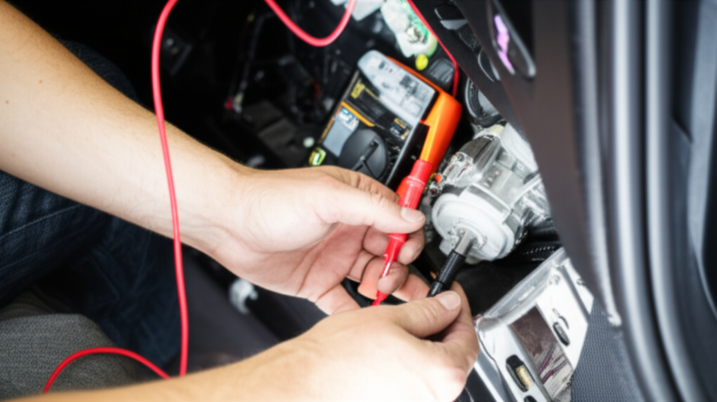
Step 5: Test for power and ground at the connector
If the resistor tests bad you found your culprit. If not then verify the circuit. This part requires live testing so reconnect the Battery.
- Set the Multimeter to DC Volts.
- Back-probe the power input wire at the resistor harness. Turn the fan on. You should see Battery voltage at least on one speed. If you do not then check the Fuse Box and the blower motor Relay. Also check the Fan Speed Switch or the Climate Control panel.
- Check the Ground Wire. Clip the black lead to a clean chassis ground and probe the harness ground with the red lead. You should see near zero volts. If you see a high reading the ground is weak or open. You can also check voltage drop by placing one probe on the harness ground and the other on the chassis while the fan runs. Anything over 0.2 V indicates a ground issue.
- Test voltage at different fan speed settings. Watch how the voltage changes at the output to the blower motor. On classic resistors you will see lower voltage on lower speeds. On PWM systems you might still see close to 12 V yet the duty cycle changes which needs a scope to verify. A Scan Tool that reads HVAC data can also help you confirm the Climate Control command.
- Optional: Power Probe or fused jumper. You can power the blower motor side of the harness briefly to see if the Blower Motor runs. Only do this if you know the pinout. Always use a fused lead.
Two quick diagnostic tips:
- If you have power and ground at the resistor input yet nothing goes to the motor on any setting the resistor or module is bad.
- If you have no power at the input the fault lies upstream. Check the fan switch. Check the relay. Check the fuse. Check for an open circuit in the wiring.
Step 6: Reinstall and test
- Reinstall the resistor or module. Tighten the screws snug. Do not overtighten into plastic.
- Plug the connector in firmly. If the connector is loose replace the terminal ends. A loose fit causes heat and intermittent blower operation.
- Turn the Ignition Key on then run through all fan speed settings. Listen for smooth operation. Check that airflow changes at each speed.
- If you replaced a failed resistor I recommend a quick current draw test on the Blower Motor. A worn motor will take out your shiny new resistor again.
Interpreting Your Test Results: Is Your Resistor Bad
At this point the data tells the story.
Clear signs it failed
- The thermal fuse shows OL or no continuity.
- One or more resistor paths read OL. The blower motor only worked on high which bypassed the resistor bank.
- You found obvious burn marks on the resistor pack or melted plastic on the connector.
- On control modules you have power and ground present. The climate control is sending a command. The fan still does nothing or acts erratic. The module likely failed internally.
What to check if it tests good
If the blower motor resistor tests good then the problem sits elsewhere. I go down this list:
- Blown fuse in the Fuse Box. Do a proper circuit diagnosis before you just throw another fuse in. Find what caused it.
- Faulty blower motor Relay. Swap with a like relay if available for a quick check.
- Bad Blower Motor. Spin the fan by hand. If it feels rough or tight the motor is suspect. Check current draw on high speed. Many passenger car blowers should pull roughly 10 to 20 amps. A stiff motor can draw more which kills resistors. Specs vary so confirm with a Service Manual.
- Fan Speed Switch or Climate Control head unit. A worn switch can fail to send power to the resistor pack.
- Wiring Harness or Electrical Connector damage. Look for breaks near the hinge of the glove box and in the Passenger Footwell. Water leaks can corrode pins and cause intermittent blower motor operation.
- Open ground. A poor ground will make a blower motor act possessed. Do a ground wire testing routine with a voltage drop test.
- In rare cases a Control Module on the HVAC network sets a Diagnostic Trouble Code. Scan the system for HVAC DTCs if your car supports it.
I once chased a no airflow complaint on a pickup where every part tested fine on the bench. The fix turned out to be a ground eyelet hidden under carpet. It looked clean but the body seam had light rust. I cleaned it. The blower came back to life and never misbehaved again.
Replacing a Faulty Blower Motor Resistor
Why replacing it matters
I never bypass a blower motor resistor. That trick might make the fan run on high which feels like a win for a minute. It also defeats safety features and can overheat wiring. Replace the resistor or module with the correct part. If the Thermal Fuse is the only bad piece you might see videos on replacing just the fuse. That can work with proper crimped connections and the exact temperature rating yet I prefer the entire assembly for reliability.
Replace melted connectors and terminals. A new resistor plugged into a loose or burnt connector will fail early. I know it adds a few dollars yet it saves you from a repeat failure.
Always evaluate the Blower Motor. Listen for bearing noise. Check for debris in the squirrel cage. Verify current draw. A dragging motor is the number one reason resistors and control modules cook themselves. Fix the cause or you will see the same problem soon.
OEM vs aftermarket considerations
I lean OEM for resistors and modules because the calibration and thermal protection often match the vehicle better. Aftermarket parts can work fine on many models. Read reviews and choose reputable brands. Avoid no-name modules that run hot out of the box. A few dollars saved today can cost you a melted connector next month.
Frequently Asked Questions (FAQs)
Q: How much does a blower motor resistor replacement cost
A: Parts range from about 20 to 60 USD for basic resistor packs. Solid-state blower control modules often run 80 to 200 USD. Add a connector pigtail if yours is melted which can add 10 to 25 USD. Labor time ranges from 0.3 to 1.0 hour on most cars.
Q: Can I drive with a bad blower motor resistor
A: You can drive the car if the only symptom is that the fan works only on high. You will not damage the engine. You might fog windows in the rain without defrost though. If wiring or the connector smells burnt stop and fix it before you melt more parts.
Q: Is it safe to bypass a blower motor resistor
A: I do not recommend it. Bypassing defeats safety and can overload wiring. Use proper diagnostics and replace the faulty resistor or module.
Q: How long do blower motor resistors last
A: Many last the life of the car if the blower motor stays healthy. I see failures more often after 8 to 12 years or after blower motors start to draw extra current. Dust and leaves accelerate the process.
Q: What is the difference between a resistor pack and a control module
A: A resistor pack uses fixed resistors to drop voltage for lower speeds. High speed bypasses the resistors. A control module uses electronics and Pulse Width Modulation to regulate power smoothly across all speeds. Modules run cooler when everything else is healthy yet they can fail in more complex ways.
Real-World Diagnostic Patterns You Can Use
Here are quick patterns I rely on during HVAC system checks:
- Blower motor only high speed. I test the resistor first. Thermal fuse or a lower speed element is open. Visual inspection often shows discoloration or cracks.
- Intermittent blower motor. I wiggle the connector and the harness. If the fan flickers I repair the terminals or replace the connector.
- No blower on any speed. I check the fuse then verify power at the resistor input. If no power I check the fan switch and relay. If I have power and ground at the resistor output to the motor I check the motor itself.
- Resistor overheating or burnt smell. I confirm the blower motor current draw and look for airflow blockage. I replace the resistor and the connector if damaged then clear debris from the housing and the cabin filter.
- Vehicles with integrated control modules. I check for solid 12 V supply and a known good ground at the module. I verify climate control commands. If the module has power and ground yet the fan is dead or erratic the module likely failed. A PWM signal check with a scope seals the deal if I have that tool on hand.
Pro Tips for Accurate Readings
- Calibrate your expectations. Many resistors measure under 3 ohms on the lower speeds. Your meter leads and technique matter. Touch the probes together to see the lead resistance then mentally subtract that small number from your readings.
- Do a voltage drop test under load. Testing an open circuit at rest can lie to you. If the blower runs measure voltage from the positive battery terminal to the resistor’s power input. Then measure from the resistor ground to the negative battery terminal. Each should be under a few tenths of a volt. High drop means a bad connection.
- Do not forget the cabin air filter. A clogged filter reduces airflow over the resistor pack which leads to overheating.
- Use a Service Manual when you can. A correct resistor pinout diagram removes guesswork which saves time and avoids mistakes.
- Keep spares in mind. A known-good relay or a fused jumper wire can speed up diagnosis.
Common Missteps I See and How to Avoid Them
- Replacing the resistor without inspecting the Blower Motor. The new part fails again because the motor is the root cause.
- Ignoring a melted connector. Heat-damaged terminals create high resistance which makes fresh parts run hot.
- Measuring resistance on a complex PWM module then calling it good. Those numbers can mislead you. Confirm power ground and control signal.
- Using a giant paper clip to back-probe. You spread terminals then the connection becomes intermittent. Use proper probes or insert from the wire side gently.
- Skipping the fuse check. Sometimes the simplest fix is the one that works.
A Short Walkthrough Example
Let me share a quick timeline from a real job. The complaint was “fan works only on high” on a mid-size sedan.
- I dropped the glove box and saw the resistor block with a four-wire connector.
- The connector looked slightly brown. Not melted yet clearly hot at some point.
- I unplugged the resistor and tested the thermal fuse. OL. The lower speed elements also read OL. The high-speed path bypassed the failed fuse which explained the symptom.
- I checked the blower motor current with a clamp ammeter on high. It pulled 21 amps where the spec called for about 14 to 16. The motor sounded rough.
- I replaced the blower motor the resistor and the connector pigtail. I cleaned debris from the housing and installed a new cabin air filter.
- The fan worked on all speeds. Current draw dropped into spec. The customer stayed warm in winter and cool in summer.
That is the loop I want you to follow. Test. Confirm. Fix the cause. Prevent a comeback.
Conclusion: Diagnosing Your HVAC Fan Issues with Confidence
You can test a blower motor resistor at home with basic tools. Start with a visual inspection. Use your Multimeter to check continuity on the thermal fuse and the resistor elements. Verify power and ground at the harness with the fan switch on. If the resistor fails those checks replace it and inspect the Blower Motor for excessive current draw. If the resistor tests good shift your focus to the fuse relay fan switch wiring or the motor itself. Keep safety top of mind and your approach methodical. You will find the fault without guesswork.
Internal link self-check
- motor principle: used once
- stator and rotor: used once
- stator core lamination: used once
- rotor core lamination: used once
Total internal links: 4 within the required range of 3 to 5.