How to Test a Motor Starter Capacitor: A Comprehensive DIY Troubleshooting Guide
Every engineer meets this problem sooner or later. A single-phase AC motor hums but refuses to spin. The circuit breaker trips. A blower starts slowly and runs hot. You suspect the starter capacitor. You need a safe, reliable way to confirm it fast and decide what to do next without risking a motor burn out or an extended outage.
You’re in the right place. This guide walks you through how a motor starter capacitor works, the safety steps you must take, the exact tests to run with a digital multimeter, and how to interpret the results. We’ll also cover what to buy if replacement makes sense, when to call a pro, and where to look next if the capacitor checks out. Along the way, I’ll explain the engineering fundamentals in plain language so you can move with confidence.
Before we dive in, here’s a quick map.
In This Article
- Understanding Your Motor Starter Capacitor: Why It’s Crucial
- Essential Safety First: Before You Begin Any Testing
- Tools You’ll Need for Capacitor Testing
- Step-by-Step Guide to Testing Your Motor Starter Capacitor
- Interpreting Your Motor Starter Capacitor Test Results
- What to Do if Your Motor Starter Capacitor Is Bad
- If the Capacitor Tests Good: What Else to Check
- Engineering Fundamentals: Why Start Capacitors Work
- Frequently Asked Questions (FAQs)
- Your Engineering Takeaway
Understanding Your Motor Starter Capacitor: Why It’s Crucial
A motor starter capacitor stores electrical energy and releases it to create a phase shift for a single-phase AC motor during startup. Think of it like a sprinter’s starting block. Without it, the motor can’t generate enough starting torque. The rotor stalls, the motor hums, and current surges. You waste energy and risk the windings.
Two families of capacitors show up in these systems.
- Start capacitors: Intermittent duty components. They provide a large boost in microfarads (µF) for a short time during startup. Common in compressors, well pumps, HVAC units, and garage door openers.
- Run capacitors: Continuous duty components. They stay in the circuit to improve efficiency and power factor while the motor runs. Their µF values are lower than start caps. They’re critical in fan motors and many induction motor applications.
Know which one you’re testing. The process looks similar yet the expected values and tolerances differ. Start caps often have higher tolerance ranges ±20% is common. Run caps typically hold tighter tolerances like ±5% or ±10%.
Common signs of a failing motor starter capacitor:
- Motor hums but won’t start
- Motor clicks but doesn’t turn
- Slow or delayed motor start
- Frequent tripping of a circuit breaker
- Burning smell, visible swelling, or leak at the capacitor
- Motor not spinning in appliances like washing machines, pool pumps, or furnace blowers
These symptoms are strong clues. They don’t prove the root cause. You need a test.
Essential Safety First: Before You Begin Any Testing
Capacitors store energy. Even a small one can deliver a nasty shock. Follow safe electrical testing practices every time.
- Power disconnection: Turn off the power at the circuit breaker or disconnect switch. Use lockout/tagout procedures when appropriate. Verify zero voltage at the motor terminals with your multimeter before touching anything.
- Personal protective equipment (PPE): Wear insulated gloves and safety glasses. You’re dealing with stored energy and live circuits during verification.
- Capacitor discharge: Discharge the capacitor before you test or disconnect it.
- Preferred method: Use a discharge resistor such as a 2 kΩ to 20 kΩ, 5 W to 10 W resistor with insulated leads. Hold it across the terminals for 10 to 30 seconds. Check voltage approaches zero.
- Last resort: Some technicians short the terminals with an insulated screwdriver. It will spark and can damage the part or your tool. Use this only if you have no better option and only after you remove power and verify zero volts at the terminals.
- Verify discharge: Set your multimeter to DC volts and measure across the capacitor terminals. It should read near zero.
Work slow. Keep one hand in your pocket when possible to reduce shock current through your chest. If you’re uncertain about any step, call a licensed electrician or HVAC technician.
Tools You’ll Need for Capacitor Testing
Here’s the short list:
- Digital multimeter with capacitance function (µF). Many DMMs include this. It’s the most direct way to check a capacitor’s value.
- Optional dedicated capacitance meter. Useful for higher precision.
- ESR meter for capacitors. Helpful for run capacitors and deeper diagnostics yet not required for a basic pass/fail.
- Insulated screwdriver and needle-nose pliers. For opening panels and carefully removing terminals.
- PPE: Safety glasses and insulated gloves.
- Marker or phone camera. Record wire positions on the capacitor before removal.
No capacitance function on your meter? You can still perform an Ohms test for capacitor health. It won’t give a µF reading yet it can identify a shorted or open circuit capacitor. I’ll cover that in the test steps.
Step-by-Step Guide to Testing Your Motor Starter Capacitor
Follow the procedure end to end. Don’t skip steps.
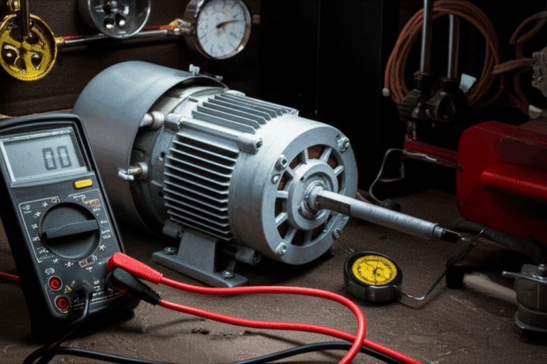
Step 1: Isolate and De-Energize the Motor
- Locate the motor and its power source.
- Switch off the main power at the breaker or disconnect.
- Use a multimeter to verify zero voltage at the motor terminals and at the capacitor terminals. Don’t trust a switch position alone.
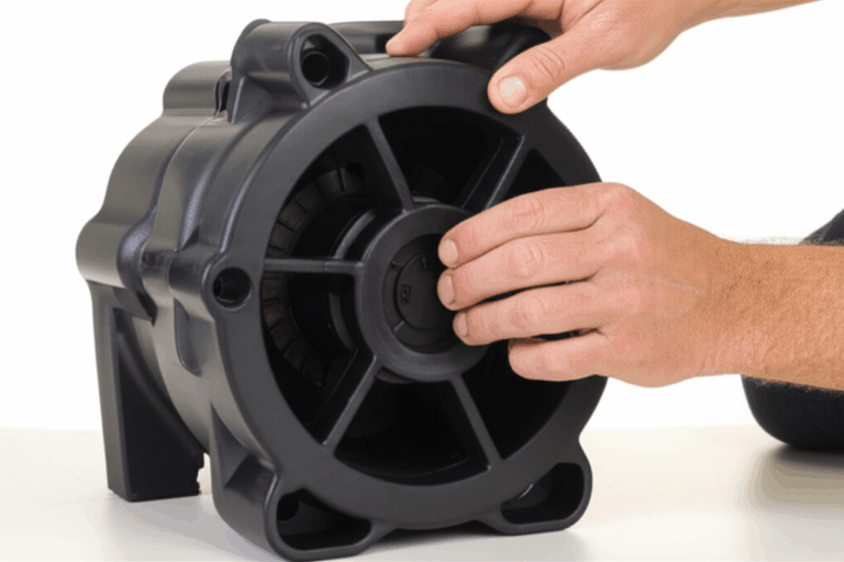
Step 2: Access and Visually Inspect the Capacitor
- Open the access panel to expose the capacitor. You’ll find it near the motor or in the control box for HVAC compressors, well pumps, garage door openers, and washing machines.
- Look for visible failure signs:
- Bulging top or bottom
- Oil leakage or discoloration
- Scorch marks
- Cracked casing
- Melted or corroded terminals
- If you see physical damage, plan to replace it. It’s unsafe to reuse.
Step 3: Safely Discharge the Capacitor
- Use a discharge resistor across the terminals for 10 to 30 seconds.
- Confirm with your multimeter set to DC volts. It should read near zero.
- If you lack a resistor and you choose to short the terminals with an insulated screwdriver, do it once, briefly, and away from your face. Expect a pop. Recheck voltage.
Step 4: Disconnect the Capacitor Wires
- Take a photo or label the wires. Note terminal markings like “C,” “HERM,” and “FAN” on dual run capacitors.
- Remove the wires with needle-nose pliers. Don’t pull on the wires. Pull on the terminals.
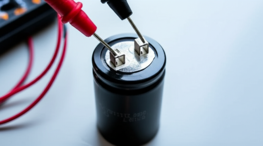
Step 5: Measure Capacitance with Your Multimeter
- Set your multimeter to the capacitance function µF.
- Connect one probe to each terminal. Polarity usually doesn’t matter for non-polar AC motor capacitors because they’re non-polarized.
- Wait for the reading to stabilize.
- Compare the measured µF value to the capacitor’s nameplate rating. Check the tolerance printed on the label when available.
- Typical tolerances:
- Start capacitors: often ±20%
- Run capacitors: often ±5% or ±10%
Step 6: Optional Resistance Check for Shorts and Opens
- Set the multimeter to Ohms or Continuity.
- Place probes across the terminals.
- Good capacitor: You’ll see a brief low resistance that rises quickly to “OL” or a very high resistance as the capacitor charges from the meter. That indicates no hard short or open.
- Shorted capacitor: It shows very low or near-zero resistance continuously. Expect breaker trips and possibly a humming motor that doesn’t start.
- Open circuit capacitor: It reads “OL” immediately and never moves. The motor hums without turning.
Step 7: Optional Leakage or ESR Check
- If you have an ESR meter or insulation resistance tester, you can check leakage or equivalent series resistance. High ESR in a run capacitor can indicate degradation even if capacitance looks close. For start capacitors, open circuit failure dominates.
Interpreting Your Motor Starter Capacitor Test Results
Here’s how to interpret what you measured.
- Good capacitor:
- Measured µF value sits within the printed tolerance. For start caps, ±20% is common. For run caps, ±5% to ±10% is common.
- No visible swelling, cracking, or leakage.
- Continuity test shows a momentary resistance change then an open as it charges.
- Bad capacitor:
- Open circuit: The most common failure mode for start capacitors. Your DMM reads 0 µF or “OL” in capacitance mode. The Ohms test shows an immediate “OL.” The motor hums but won’t start.
- Short circuit: Less common yet more dramatic. DMM shows near zero Ohms. The breaker trips. You may hear a click followed by silence.
- Degraded capacitance: The µF reading drops well below nameplate. The motor starts slowly, overheats, or runs inefficiently. A 50% drop creates serious starting issues.
- Visible damage: Bulging, leaking, scorch marks. Replace it regardless of meter readings.
Field data and failure analysis align with what technicians see every day. Start capacitors most often fail open. Run capacitors drift in value or increase in ESR over time. Heat shortens life. As a rule of thumb, every 10°C rise in ambient temperature can slice life roughly in half. Duty cycle, voltage stress, and part quality matter too.
Costs and service considerations:
- Replacement part cost: $10 to $50 for most start capacitors. Run capacitors sit in a similar range depending on µF and voltage.
- Professional service call: $100 to $350 including labor and part. DIY saves money if you follow safe practices and you’re comfortable with the work.
What to Do if Your Motor Starter Capacitor Is Bad
If your test points to a bad capacitor, replace it with a unit that matches the application.
- Match the capacitance (µF): Use the exact capacitance rating on the label. For start capacitors, a wrong value will change starting torque and can stress the motor.
- Voltage rating: Choose equal or higher voltage. Never go lower. A 250 VAC capacitor can replace a 220 VAC unit if physical size and form factor fit.
- Tolerance: Check the tolerance requirement for your design. ±20% is common for start caps. Tighter tolerance benefits some applications.
- Duty and temperature rating: Start capacitors are intermittent duty. Run capacitors are continuous duty. Select by application. Confirm ambient temperature rating and expected run conditions. Hot enclosures demand better thermal margin.
- Case style and mounting: Confirm the can size, mounting bracket, and terminal style. Some units use spade terminals. Others use screw terminals. Make sure the replacement fits the space and the mounting orientation.
- Compliance and documentation: For procurement teams, request UL file numbers when applicable. Confirm RoHS or REACH compliance as required. Ask for batch test data for critical projects.
- Quality and supplier reliability: Start capacitors are low cost yet high consequence. Cheap parts fail early. Work with suppliers who can provide traceability and consistent performance.
Capacitor replacement process in brief:
- Isolate power. Discharge and remove the old part.
- Install the new capacitor. Reconnect wires to the correct terminals based on your photo or diagram.
- Re-energize and test the motor. Verify proper start behavior and listen for abnormal noise.
If you’re unsure about wire positions on dual run capacitors labeled “C,” “HERM,” and “FAN,” consult the equipment wiring diagram. The wrong connection can damage a compressor motor or blower.
If the Capacitor Tests Good: What Else to Check
Sometimes the capacitor isn’t the culprit. If you get a good reading within tolerance and no visible damage, shift your troubleshooting.
- Supply voltage and wiring:
- Verify the line voltage at the motor matches nameplate requirements.
- Check for loose connectors, corroded spade terminals, and damaged wires.
- Confirm the circuit breaker or fuse size is correct.
- Motor windings and overload:
- Perform a motor winding resistance test. Measure the start and run windings. Compare to the manufacturer’s specs.
- Check for open circuits or shorts to ground.
- Verify the overload protection device or thermal switch resets properly.
- Start circuit controls:
- For split-phase or capacitor start motors, a centrifugal switch or potential relay removes the start capacitor from the circuit after startup. If that switch or relay fails, the motor may hum or overheat.
- Inspect and test the centrifugal mechanism for mechanical binding and the relay for proper operation.
- Mechanical load and bearings:
- Check for seized bearings, foreign objects, or misalignment. A good capacitor won’t overcome a locked rotor due to mechanical drag.
- Application-specific checks:
- HVAC: Check the fan run capacitor and compressor run capacitor if present. Test the contactor and control board outputs. A weak run capacitor can mimic a bad start.
- Well pump: Inspect pressure switch contacts and wiring splices in the well head box.
- Washing machine: Confirm the motor coupler or belt hasn’t failed.
- Garage door opener: Verify travel limits and balance of the door. A heavy or unbalanced door overloads the motor.
Design note for engineering teams:
- Motor starting performance depends on more than the capacitor alone. Stator and rotor design, slot geometry, electrical steel grade, and lamination quality all influence starting current and torque. The quality of the stator core lamination and the matching rotor core lamination strongly impact efficiency and thermal behavior under start conditions.
Engineering Fundamentals: Why Start Capacitors Work
Let’s strip it to fundamentals. A single-phase induction motor doesn’t naturally create a rotating magnetic field at standstill. The start capacitor injects a phase shift between current in the start winding and current in the run winding. That phase shift produces a rotating magnetic field which creates torque on the rotor. Once the rotor accelerates, the start circuit disconnects.
- Capacitance and phase shift:
- A capacitor resists changes in voltage. Current leads voltage in a capacitive circuit. This lead introduces the needed phase shift in the start winding.
- Capacitive reactance decreases as frequency increases. In AC motors, the actual frequency is fixed at the mains. The selected µF value sets the phase shift at that frequency.
- Start capacitor vs run capacitor:
- Start capacitors provide high µF for a short time to maximize starting torque. They’re not built for continuous duty.
- Run capacitors provide lower µF yet operate continuously. They improve power factor and smooth the torque ripple.
What about the core itself? Your motor’s magnetic circuit uses laminated electrical steel to minimize eddy current and hysteresis losses. Think of eddy currents as unwanted whirlpools in a river. Thin, insulated laminations break those whirlpools into tiny eddies that waste far less energy. Choosing the right grade of electrical steel laminations and managing lamination thickness helps keep core losses in check. Better lamination design reduces heat rise and improves efficiency during both start and run.
Core losses come in two buckets:
- Hysteresis loss: Energy lost as the magnetic domains flip direction each cycle. It scales with frequency and depends on material coercivity which is the resistance to demagnetization.
- Eddy current loss: Currents induced in the core that create heat. Thinner laminations and proper insulation reduce these currents.
Great lamination design pairs with the right capacitor. You get clean starts, lower inrush, and better reliability. For teams balancing design tradeoffs or building to cost, align capacitor selection with the motor’s laminated core and winding strategy. If you don’t, you invite edge cases like motor hum at startup or nuisance breaker trips.
For procurement managers planning platform consistency, lock in both capacitor and lamination specifications early. Then hold suppliers to those specs for repeatable performance across builds. Coordinating with a trusted lamination partner on the motor core laminations can stabilize your start-up performance across product families.
Frequently Asked Questions (FAQs)
Q: How often do motor capacitors need replacement?
- A: Typical lifespan ranges from 3 to 10 years with wide variation. Heat is the primary life limiter. A rough rule says every 10°C rise in ambient temperature can halve lifespan. High duty cycles and voltage stress shorten life. Good design and good parts last much longer.
Q: Can a motor run without a start capacitor?
- A: Most single-phase induction motors that require a start capacitor will not start without it. Some designs may eventually creep in the right direction due to asymmetry, yet they draw heavy current and overheat. Don’t run it that way.
Q: What’s the difference between a start and run capacitor?
- A: Start capacitors are intermittent duty with high µF values to produce a strong phase shift at startup. Run capacitors are continuous duty with lower µF values to improve running efficiency and power factor.
Q: Can I test a capacitor without removing it?
- A: You can measure voltage or look for obvious faults in place. For accurate capacitance testing, disconnect at least one lead so parallel circuits don’t skew the reading. Testing in-circuit can mislead due to other paths.
Q: What if my multimeter doesn’t have a capacitance function?
- A: Use the Ohms test to identify shorts or opens. You can also use a dedicated capacitance meter. An ESR meter helps evaluate run capacitors. As a last resort, try substitution with a known-good part if the application allows.
Q: Does polarity matter?
- A: AC motor start and run capacitors are non-polar for alternating current. Polarity doesn’t matter for measurement or installation. DC electrolytic capacitors are polar. Don’t substitute a polar electrolytic where a non-polar AC capacitor is required.
Q: Why do capacitors fail?
- A: Heat, overvoltage, mechanical vibration, manufacturing defects, and poor quality control lead the list. Start capacitors commonly fail open. Run capacitors tend to drift out of tolerance or develop high ESR.
Q: What about ESR?
- A: Equivalent Series Resistance represents internal losses in the capacitor. High ESR raises heat and reduces effective capacitance under load. It’s more useful for diagnosing run capacitors. A dedicated ESR meter provides the best read.
Q: How much does replacement cost?
- A: Parts generally cost $10 to $50. Professional replacement including diagnostics lands around $100 to $350 depending on region and equipment.
Q: Are hard start kits different?
- A: Hard start kits add a start assist capacitor and typically a relay. They boost starting torque on HVAC compressors and similar loads. They can solve marginal starts due to voltage drop or aging components. Use them when the equipment manufacturer approves.
Your Engineering Takeaway
Here’s the short list you can keep on your bench.
- Confirm symptoms before testing: hums but won’t start, slow start, breaker trips, burning smell.
- Lock out power and verify zero volts. Discharge the capacitor with a resistor. Check voltage near zero before proceeding.
- Use a DMM with capacitance. Compare µF to nameplate and tolerance. For start caps, ±20% is common. For run caps, ±5% to ±10% is typical.
- Run an Ohms test. A good capacitor shows a brief resistance change then goes open. A shorted unit reads near zero Ohms. An open unit reads “OL” immediately.
- Replace bad capacitors with the same µF and an equal or higher voltage rating. Match duty, temperature rating, case, and terminals. Confirm compliance needs.
- If the capacitor looks good, check supply voltage, motor winding resistance, start controls like centrifugal switches or relays, and mechanical load.
- Remember the bigger system. Laminated core design and winding strategy influence starting performance and thermal behavior. Align capacitor selection with your motor’s core and winding design for consistent starts.
If you’re designing or sourcing motors across a platform, bring the capacitor specification into your design rules early. Coordinate with your lamination partner to ensure the magnetic circuit supports your starting torque targets. For deeper dives or to explore lamination options for BLDC prototypes and AC induction motors, review the fundamentals of core lamination stacks and how they interact with winding and capacitor choices.
Below you’ll find a more detailed, engineer-focused walkthrough that adds context and practical nuance. Use it to refine your internal procedures, train field techs, and standardize replacement criteria across teams.
Deeper Dive: The Practical Testing Playbook
- Motor capacitor troubleshooting starts with symptom matching:
- Motor not spinning or starts slowly
- Motor hums but won’t start
- Nuisance circuit breaker trips during start
- Burning smell or visible smoke near the capacitor housing
- Safety and preparation:
- Cut power. Verify zero voltage with your multimeter. Don’t assume.
- PPE on. Discharge with a resistor. Verify voltage is near zero.
- Label or photograph the wiring so reassembly is error-free.
- Capacitance measurement method:
- Multimeter capacitance function gives you a direct microfarad reading. It’s the gold standard for a quick field check.
- Compare against the nameplate on the capacitor. Respect the tolerance stamped on the can.
- A reading that sits outside the tolerance range indicates a failed or failing part.
- Alternative tests when you lack a capacitance function:
- Resistance test on Ohms: Expect a short pulse then a rise to open circuit for a healthy unit.
- Voltage drop check after applying a known charge and timing the decay can work on the bench. It’s less convenient in the field. Avoid this if you have better tools.
- Interpreting common failures:
- Open circuit capacitors dominate start capacitor failures. These present with motors that buzz but never catch.
- Short circuits trip breakers instantly.
- Weak capacitance shows up as slow starts and overheating. The motor pulls heavy current which harms windings over time.
- Advanced diagnostics:
- ESR meter for run capacitors. Elevated ESR may cause fans to run slow with extra noise. You will also see higher operating temperatures.
- Leakage checks on an insulation resistance tester help with borderline cases or critical equipment.
- Replacement tips that reduce repeat failures:
- Choose capacitors with appropriate temperature ratings. Hot rooftops and furnace enclosures punish marginal parts.
- Verify the voltage rating and add margin if line conditions vary.
- Secure the capacitor with the correct mounting bracket. Vibration kills. Proper mounting extends life.
- Confirm the motor’s centrifugal switch or potential relay functions. A stuck relay leaves the start cap in circuit and cooks it.
- Procurement guidance:
- Standardize on reputable brands and keep spares on hand for HVAC, well pumps, and essential appliances. Stock the common µF and voltage values that align with your installed base.
- Request datasheets and lot traceability for volume purchases. Ask for test reports on capacitance tolerance and leakage across temperature extremes when your application justifies it.
- For long-term reliability, align capacitor specs with the motor’s core materials. Temperature rise ties directly to core loss and coil heating. Better lamination material and stack design produce a cooler, more forgiving environment for the capacitor during repeated starts.
Cross-Checks and Related Topics Engineers Ask About
- Can a supply drop mimic a bad capacitor?
- Yes. Low line voltage reduces starting torque as quickly as a weak start capacitor does. Measure voltage under load at the motor terminals.
- What about phase shift accuracy?
- The correct µF value sets the phase angle between start and run windings. Too low and you lose torque. Too high and you elevate current and stress components.
- When do I consider a hard start kit?
- For marginal conditions like long line runs to an outdoor condenser or aging compressors. It can improve startup reliability. Follow OEM guidance.
- How do laminations factor in motor starts?
- Core losses convert to heat during start when current is high. Better material and thin lamination stacks reduce losses and temperature rise. This gives you more margin for repeated starts and extends component life. If you’re designing the motor, consider the grade and thickness of laminations along with your start and run capacitor strategy.
- Where can I learn more about lamination types and performance tradeoffs?
- Start with overviews on electrical steel laminations. Then dig into stator and rotor design impacts on torque, efficiency, and thermal limits. That foundation helps you specify capacitors that complement the magnetic circuit.
Realistic Expectations: Lifespan, Cost, and Risk
- Typical lifespan for start and run capacitors spans 3 to 10 years in general service. The range widens with heat, cycling, and part quality. I have seen parts fail in a single year in hot, enclosed spaces with high start frequency.
- Replacement parts are inexpensive compared to the motor. The labor and downtime dominate total cost.
- Risk concentrates during start. Motors draw high current and generate heat if they don’t spin up quickly. A weak or open start capacitor pushes you into that danger zone fast. Don’t let it linger.
Final Words on Safety
- Use lockout/tagout when you control the upstream disconnect. Confirm with a meter. Always verify zero energy before you touch.
- Discharge capacitors before testing or removal. Prefer a resistor. Verify with the meter. Treat it as a habit you never skip.
- If you face an unknown wiring configuration or a control box with multiple capacitors and relays, stop and get the wiring diagram. Guessing costs more than waiting.
Closing the Loop: From Diagnosis to Decision
You started with a motor problem. You now have a tested capacitor and a clear result. Either it’s within tolerance and physically sound or it’s not.
- If it’s bad, replace it with a matching µF and equal or higher voltage rating. Lock in duty rating, temperature rating, and compliance. Verify correct wiring on installation.
- If it’s good, expand your troubleshooting to wiring, supply voltage, start controls, and mechanical load. Confirm motor winding resistance and insulation. Then evaluate the design context if you keep seeing repeat failures.
The motor design and its magnetic circuit set the stage. The capacitor brings the opening act together. When both are specified and maintained well, startup becomes routine. That consistency lets you protect windings, minimize energy waste, and extend service life. If you’re building a new platform or planning a redesign, partner early with lamination and capacitor suppliers. Define targets for start torque, inrush current, and allowable temperature rise. Then validate with prototype builds under worst-case line conditions. You will reduce field surprises and service calls.
If you’d like a quick orientation on motor core choices for new designs, review options for core lamination stacks. Tie those material and process decisions to your start and run capacitor strategy so you deliver repeatable performance at scale.
That’s the path from problem to proof. You can test with confidence, interpret results quickly, and act decisively.