How to Test an Electric Motor — And What Your Laminations Are Telling You
Every design engineer has felt this pinch. A motor won’t start, a drive draws too much current, a production line hums louder than it should. You need to test the motor right now. Yet the measurements you collect do more than clear a service ticket. They also reveal whether your stator and rotor laminations, materials, and manufacturing choices are helping or quietly hurting performance.
This guide gives you both. You’ll get a clear, step‑by‑step approach to testing AC and DC motors with a multimeter, a megohmmeter, and a few optional diagnostic tools. Then we connect the dots to laminations. You’ll see how insulation resistance, winding imbalance, and thermal behavior relate back to electrical steel grade, lamination thickness, cutting method, and stack assembly.
Use this as a practical playbook for technicians in the field, design engineers under deadline, and procurement leaders making build‑or‑buy decisions.
In This Article
- Why and When to Test a Motor
- Safety First: Essential Precautions
- Tools You’ll Use for Motor Diagnostics
- Understand Your Motor: Types, Components, Nameplate Data
- Preliminary Inspection Checklist
- Step-by-Step Electrical Testing Procedures
- Interpreting Results and What They Mean for Laminations
- Advanced Motor Diagnostics
- Troubleshooting Common Motor Problems
- Preventive Maintenance and Reliability
- Lamination Materials and Core Loss Basics
- Manufacturing Processes That Affect Test Results
- Match the Right Solution to Your Application
- Engineering Takeaways and Next Steps
Why and When to Test a Motor
Testing answers three urgent questions. Is the motor safe to energize. Is the fault in the motor or in the power system. If the motor is bad what exactly failed.
Common triggers:
- Malfunction: Motor not starting, tripping a breaker, overheating, humming, or losing torque.
- Maintenance: Preventive or predictive checks before failure.
- Pre‑installation or post‑repair validation: Confirm condition before commissioning or after rewind.
- Power quality concerns: Voltage imbalance, harmonics, or a suspect VFD setup.
Quick reality check. Studies from IEEE and EPRI attribute 40–51% of failures to bearings, 25–30% to stator windings, and the rest to rotor issues and external factors. That split should guide your testing plan. Don’t just meter the terminals. Listen for bearings. Scan for hot spots. Verify insulation health.
Safety First: Essential Precautions
Electric motors store energy. They spin up fast and they bite. Protect yourself and your team.
- Lockout/Tagout (LOTO): Apply LOTO on the disconnect. Verify zero energy with a meter. Discharge capacitors on VFDs and single‑phase motors.
- PPE: Wear insulated gloves, safety glasses, and arc‑rated clothing when applicable.
- Isolate the motor: Disconnect leads from the starter or VFD before resistance or insulation tests.
- Ground safety: Confirm the frame ground is intact. Test for ground faults before re‑energizing.
Treat every test like you would a live circuit until you prove otherwise.
Tools You’ll Use for Motor Diagnostics
You can do a lot with a basic kit. Add advanced tools when the problem hides deeper.
- Multimeter: Continuity, resistance, and voltage checks. Many meters measure capacitance for start/run capacitors.
- Megohmmeter (Megger): Insulation resistance to ground or between windings. Use appropriate test voltages per motor rating and IEEE 43 guidance.
- Clamp meter: Current draw analysis under load, starting amps, phase imbalance checks.
- Optional instruments:
- Thermal imager: Find hot spots in stator slots, end turns, bearings, and terminal boxes.
- Vibration analyzer: Bearing defects, misalignment, looseness, and mechanical resonance.
- Motor analyzer / MCA: Motor circuit analysis detects inter‑turn shorts, rotor bar problems, and winding asymmetries early.
- Growler: Armature short detection for DC motors.
- Oscilloscope or power analyzer: Power quality, voltage drop, harmonics, and VFD switching effects.
Understand Your Motor: Types, Components, Nameplate Data
Different motor types call for slightly different tests and expectations.
- Motor types:
- Single‑phase AC: Often use start and run capacitors and a centrifugal switch.
- Three‑phase AC (induction): Workhorse in industry. Three identical windings spaced 120° electrically.
- DC brushed: Brushes and commutator introduce unique wear and test points.
- Brushless DC (BLDC) and servo: Electronic commutation through a drive. Stator windings with permanent magnet rotors.
- Stepper: Discrete steps with high detent torque. Test winding resistance and inductance per phase.
- Key components you will interact with:
- Stator and windings
- Rotor and shaft
- Bearings
- Terminal block and leads
- Capacitors and centrifugal switch (single‑phase)
- Brushes and commutator (DC brushed)
- Enclosure, fan, and cooling system
- Nameplate data matters:
- Voltage, current, frequency, RPM, horsepower/kW
- Insulation class and temperature rise
- Service factor and duty rating
- Phase and connection type (Delta/Wye)
Nameplate data sets your baseline for acceptable voltage, current draw, and expected resistance ranges. It keeps you from chasing ghosts.
If you need a deeper primer on core components, the quality of the stator core lamination and the geometry of the rotor core lamination directly influence losses, torque ripple, and heat.
Preliminary Inspection Checklist
Look and listen before you meter. Many failures announce themselves.
- Physical damage: Dents, cracked housings, broken fans, missing guards.
- Wiring and connections: Loose lugs, frayed leads, overheated terminal blocks.
- Overheating signs: Discoloration on windings, cooked varnish smell, melted insulation.
- Contamination: Oil, dust, moisture ingress, or corrosive residue in the enclosure.
- Bearings: Rotate the shaft by hand. Feel for roughness or grinding. Check axial and radial shaft play.
- Cooling: Verify fan and airflow path are clear. Inspect filters and vents.
This five‑minute check often saves an hour of testing.
Step-by-Step Electrical Testing Procedures
The following procedures cover both static motor testing and dynamic checks under power. Use the right sequence. You start with safe, de‑energized tests then move to powered measurements.
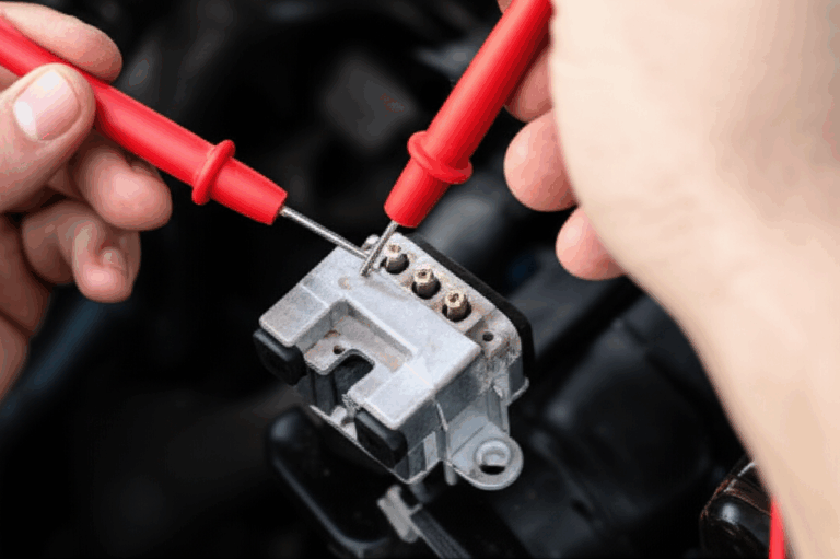
A. Winding Resistance Test (Multimeter)
Purpose: Find open circuits, shorted turns that manifest as low resistance, and phase imbalance.
- Single‑phase AC motors:
- Identify Common (C), Start (S), and Run (R) terminals.
- Measure R‑C, S‑C, and S‑R. Expect R‑C < S‑C < S‑R. The sum of R‑C and S‑C should equal S‑R within tolerance.
- Large deviations point to a winding problem or a misidentified lead.
- Three‑phase AC motors:
- Label leads T1, T2, T3. Measure resistance between each pair: T1‑T2, T2‑T3, T3‑T1.
- Readings should be nearly identical. A typical imbalance limit sits around 2–3% for many industrial motors.
- Significant imbalance suggests partial shorted turns or poor connections.
- DC motors:
- Measure between commutator bars with a low‑ohms meter or a growler for armature shorts.
- Check field winding resistance separately.
Interpretation: Open circuit shows as infinite resistance. Very low resistance compared to mates hints at inter‑turn short. Imbalance on three‑phase windings creates unequal current draw and vibration under load.
B. Continuity Test (Multimeter)
Purpose: Confirm unbroken electrical paths in windings, internal connections, and protective devices.
- Test each winding end to end.
- Verify thermal protection devices if present.
- Confirm continuity where the wiring diagram calls for it.
Open circuits usually trace to broken leads, burnt connections, or failed thermal protectors.
C. Insulation Resistance Test (Megohmmeter)
Purpose: Detect insulation breakdown to ground or between windings. Moisture, contamination, and thermal aging degrade insulation over time.
Procedure:
- Disconnect motor leads from the starter or VFD.
- Connect the Megger positive lead to a winding group and the negative to the motor frame ground.
- Apply test voltage per motor rating. IEEE 43 provides guidance. For many low‑voltage machines, 500 V or 1000 V tests are common. Follow the nameplate and company standards.
- Record the resistance after 1 minute. For larger machines measure polarization index (PI) by taking the 10‑minute value divided by the 1‑minute value.
Interpreting results:
- As a rule of thumb, you want insulation resistance well above 1 MΩ for small motors. Many fleets require 100 MΩ or higher on new or dried units.
- Low readings point to moisture, contamination, or insulation breakdown. Dry and clean if contamination is the culprit. Rewind or replace if breakdown persists.
- PI below 2 suggests moisture or contamination. Higher PI indicates healthier insulation.
D. Ground Fault Test
Purpose: Find winding insulation failure to the frame. Many meters include a dedicated ground fault or continuity mode. A low resistance path to ground means a fault. The Megger test often doubles as this check and provides better sensitivity.
E. Voltage and Current Draw Test (Under Power)
Purpose: Verify power supply and load health.
- Voltage supply check:
- Measure line‑to‑line voltage. Compare to nameplate.
- Check voltage imbalance on three‑phase. Keep it under 1%. Even small imbalances cause large current imbalance and heating.
- Current draw analysis:
- Use a clamp meter to measure current on each phase.
- Compare to nameplate full load amps (FLA).
- High current with low speed suggests mechanical load issues or internal electrical faults.
- Phase current imbalance flags winding problems, poor connections, or power quality issues.
- VFD‑driven motors:
- Confirm carrier frequency, ramp settings, and minimum speed limits.
- Check for excessive voltage drop on long cables. Use output filters if required.
F. Capacitor Test (Single‑Phase AC Motors)
Purpose: Determine the health of start and run capacitors.
- Discharge the capacitor safely with a resistor.
- Disconnect one lead.
- Set your meter to capacitance mode and measure. Compare to the capacitor’s labeled value and tolerance.
- Replace if out of spec or if ESR (equivalent series resistance) tests fail.
G. Additional Checks That Solve Puzzlers
- Centrifugal switch test: Verify actuation and contact condition. A stuck switch keeps the start winding engaged and cooks it.
- Motor rpm test: Use a tachometer. Compare to nameplate RPM. Large slip change under load hints at rotor issues in induction motors.
- No‑load and loaded performance: Check current, temperature rise, and vibration at no‑load and under a representative load.
- Voltage drop test: Measure at the motor terminals and compare to the supply. Excessive drop can cause high current draw and poor starting torque.
- Back EMF and inductance checks: Some analyzers measure inductance balance and back EMF symmetry. Imbalances expose inter‑turn shorts early.
Interpreting Results and What They Mean for Laminations
Your readings tell a story. Here’s how to read it like a pro and link it to core material and manufacturing choices.
- Low insulation resistance with normal winding resistance:
- Likely moisture or contamination. Dry the motor and retest.
- Persistent low IR may indicate thermal damage to the winding varnish and slot liners. High core temperatures accelerate insulation aging. Better core material and optimized lamination thickness reduce core losses and heat which protects insulation life.
- Phase resistance imbalance with higher current on the lowest‑resistance phase:
- Points to shorted turns. Heat becomes localized in that phase. Poor slot geometry or burrs from punching can nick insulation on slot edges. Laser cutting minimizes burrs but introduces a heat‑affected zone unless controlled.
- Motor overheats at normal load with balanced currents:
- Think core losses. Eddy currents and hysteresis losses rise with poor electrical steel grade, excessive lamination thickness, or damaged interlaminar insulation. Inadequate varnish fill can also add loss.
- Upgrading to higher grade electrical steel with proper coating and tighter thickness control often cuts heat at the source.
- Loud hum with torque ripple under load:
- Inspect rotor. Broken or cracked bars in induction motors cause characteristic current signatures. Poor rotor lamination stacking and casting porosity worsen the issue. Mechanical eccentricity from loose stacks or misaligned laminations adds vibration.
- Voltage imbalance and high current without obvious winding damage:
- Fix the power quality first. Even a 1% voltage imbalance can produce about 6% current imbalance and significant temperature rise. Protect good motors from bad power.
- Bearing noise and elevated vibration:
- Bearings cause about half of failures in studies by IEEE and EPRI. Vibration analysis and thermal imaging catch early defects. Electrical discharge machining (EDM) from VFD common‑mode currents damages bearings. Shaft grounding and insulated bearings reduce risk.
Link these patterns back to procurement decisions. Material selection and process control at the lamination level shape thermal performance, efficiency, and reliability metrics.
For a deeper dive on core types used in motors, this overview of motor core laminations maps common architectures to typical performance tradeoffs.
Advanced Motor Diagnostics
Sometimes the simple tests pass and the motor still misbehaves. Bring in the advanced methods.
- Vibration analysis: Detect bearing faults, misalignment, looseness, and rotor eccentricity. Envelope analysis and spectral peaks locate the culprit.
- Thermal imaging: Scan stator slots, end windings, and bearings under load. Hot spots tell you where losses concentrate.
- Motor Circuit Analysis (MCA): Inject low‑voltage signals to measure impedance, inductance, and phase angle. MCA detects inter‑turn shorts and rotor issues earlier than current alone.
- Motor Current Signature Analysis (MCSA): Analyze current waveforms to infer air‑gap eccentricity, broken rotor bars, and load anomalies.
- Surge comparison testing: Identify turn‑to‑turn insulation weaknesses in stator coils and windings.
- Growler test: The classic method for DC armature shorts.
- Power quality analysis: Harmonics, sags, swells, and unbalance drive nuisance trips and overheating.
IEEE and industry experience suggest MCA can detect a high percentage of winding faults in early stages. That window gives you time to plan rather than react.
Troubleshooting Common Motor Problems
Use this field‑tested logic. Start simple. Move to targeted tests as you rule things out.
- Motor won’t start:
- Check supply voltage and control circuit. Verify contactor coil and overload relay settings.
- Single‑phase: Test start capacitor and centrifugal switch.
- Three‑phase: Confirm phase presence and sequence. Measure winding resistance for opens.
- Motor hums but doesn’t turn:
- Single‑phase: Start capacitor likely failed. Centrifugal switch might be stuck. Shaft may be seized.
- Three‑phase: Single phasing or locked rotor. Check for mechanical binding.
- Motor trips breaker or overload:
- Overload setting too low or load too high. Measure current draw.
- Insulation breakdown to ground causes ground‑fault trips. Megger test confirms.
- VFD parameters can cause high inrush or long acceleration. Tune ramps and torque limits.
- Motor overheats:
- High ambient or blocked cooling path. Clean and improve airflow.
- Voltage imbalance drives heat. Fix power quality.
- Internal losses from winding shorts or high core loss. Inspect both electrical and lamination‑related causes.
- Reduced performance or efficiency:
- Compare current draw, speed, and temperature under the same load.
- Look for rotor bar problems in induction motors if torque sags.
- Consider core loss from material choices or stack defects if temperatures trend high without obvious electrical faults.
Preventive Maintenance and Reliability
Maintenance reduces risk and cost. Aberdeen Group tracked staggering downtime costs per minute for industry and motors are a major slice of that pie. The U.S. Department of Energy reports that predictive programs can cut maintenance costs by 25–30% and breakdowns by 70–75%.
Actionable steps:
- Regular inspection schedule: Visual checks, vibration trending, and thermal baselines.
- Cleaning and lubrication: Keep enclosures, fans, and filters clean. Lubricate bearings per OEM and avoid overgreasing.
- Environmental control: Seal against moisture, dust, and corrosives. Use correct IP or NEMA enclosure types.
- Power quality: Balance phases, size circuit breakers properly, and use line reactors or filters on VFDs.
- Motor protection devices: Test overload relays, check contactor contacts, validate ground fault protection, and confirm breaker sizing.
Lamination Materials and Core Loss Basics
Now let’s connect testing outcomes to material science. Core losses come from two main sources:
- Hysteresis loss: Energy lost each time the magnetic domains flip as the field cycles. Materials with low coercivity lose less each cycle.
- Eddy current loss: The changing magnetic field induces swirling currents in the core. Those currents heat the core and waste energy.
Imagine a river forming whirlpools behind rocks. Thick, solid steel allows large whirlpools to form which heats the water around them. Thin, insulated laminations break the whirlpools into tiny eddies that carry far less energy.
Material choices:
- Electrical steels (CRNGO and CRGO):
- Cold‑rolled non‑oriented (CRNGO) silicon steels serve rotating machines well because properties are similar in all directions. Grades improve with lower core loss and higher magnetic induction.
- Cold‑rolled grain‑oriented (CRGO) steels shine in transformers along the rolling direction. You can use them in motors only in special designs with aligned flux paths.
- Coatings on each lamination provide interlaminar insulation. This coating is a big lever for eddy current reduction.
- Cobalt alloys:
- Higher saturation induction and lower losses at high frequency. Great for aerospace and compact high‑power‑density machines.
- Very expensive. Use when the performance requires it.
- Amorphous metals:
- Very low core loss at high frequency due to random atomic structure. Manufacturing constraints and brittleness limit use in many motor topologies.
- Thickness:
- Thinner laminations reduce eddy current loss. You pay with higher manufacturing cost and more complex stacking. High‑frequency applications profit the most from thin gauges.
If you’d like a compact primer on material families and how they trade off magnetics, coatings, and cost, this page on electrical steel laminations lays out the basics. If your design targets general‑purpose motors and transformers, silicon steel laminations remain your standard baseline.
Manufacturing Processes That Affect Test Results
Material sets your ceiling. Manufacturing determines how close you get.
- Punching versus laser cutting:
- Punching delivers speed for volume. Poor die condition leaves burrs that cut slot liner insulation or raise interlaminar shorts. Good die maintenance, deburring, and coatings keep losses low.
- Laser cutting enables fast prototyping and complex shapes. Heat‑affected zones can raise local loss if not managed. Secondary annealing and process control keep it in check.
- Interlocking, welding, bonding:
- Interlocking laminations works like snapping LEGO bricks together. You create a rigid stack without welding heat that can degrade properties.
- Bonding with resin or adhesive creates a solid core and reduces magnetostriction noise. Process control matters for consistency and cure.
- Welding provides robust mechanical integrity. Use sparingly or away from active flux paths to avoid local property changes.
- Stacking factor:
- Air gaps between laminations reduce effective magnetic cross‑section. Tight stacking and consistent pressure improve the stacking factor and reduce loss.
- Coating integrity:
- Each lamination needs a good insulating layer. Poor coating coverage increases interlaminar eddy currents. QC checks for coating quality pay off in lower heat during operation.
Test results to watch after manufacturing or repair:
- Elevated no‑load current and temperature rise: Often a core loss symptom linked to material grade, thickness, or manufacturing defects.
- Audible hum and vibration at multiples of line frequency: Magnetostriction and loose stacks can sing a little too loudly. Bonded stacks help.
- Early insulation resistance drift: Local hot spots from core issues cook winding insulation and reduce PI values over time.
For component‑level context, these pages on stator core lamination and rotor core lamination show how geometry and assembly influence flux paths, slot fill, and torque ripple.
Match the Right Solution to Your Application
Use the tests to pick better materials and processes. Here are typical scenarios and good‑fit choices.
- High‑frequency or high‑speed motors:
- Choose thinner laminations and higher grade electrical steel. Consider cobalt alloys if power density and thermal limits demand it.
- Expect lower eddy current loss and cooler operation at speed. Budget rises with performance.
- Industrial induction motors with VFDs:
- CRNGO silicon steel with good coatings and consistent stacking delivers strong efficiency at reasonable cost.
- Pay attention to rotor bar integrity and stack compression. Current signature analysis spots issues early.
- Precision servos and BLDC motors:
- Focus on low core loss and tight tolerances. Laser cut or precision stamped laminations with careful bonding minimize cogging torque and harmonics.
- Prototyping and low volume:
- Laser cutting provides speed and geometry freedom. Validate core loss with no‑load current and temperature tests. Consider a secondary anneal when needed.
- Mass production with cost pressure:
- High‑quality stamping wins on total cost and repeatability. Die maintenance and burr control protect winding insulation and hold efficiency.
For a broad survey of core configurations used across motor families, review this guide to motor core laminations. It ties material options to stack architectures and typical applications.
Engineering Takeaways and Next Steps
If you only remember a few things, take these with you.
- Start safe: Lockout/tagout, discharge, and isolate. Confirm zero energy.
- Build a fast test sequence:
- Visual inspection and bearing check
- Winding resistance and continuity
- Insulation resistance to ground with a megger
- Voltage and current under power
- Capacitor health for single‑phase motors
- Use advanced diagnostics when the basics pass but symptoms remain:
- Vibration analysis, thermal imaging, MCA, MCSA, surge tests, and growler for DC.
- Let results inform material and manufacturing choices:
- Overheating at no‑load hints at core loss. Upgrade electrical steel grade or reduce lamination thickness.
- Winding and slot issues often trace back to burrs or poor slot insulation. Improve punching quality or consider laser with proper process control.
- Noise and torque ripple call for tighter stacks, better bonding, or stator/rotor geometry refinement.
- Think lifecycle:
- Predictive maintenance programs pay back big. Trend insulation resistance, vibration, and thermal data. You avoid surprise breakdowns and extend service life.
Ready to translate today’s test data into a better stator or rotor stack. Bring your measurements, nameplate data, and application constraints to a technical consultation. A short review aligns your testing results with material and process recommendations then you can decide to repair, rewind, or redesign with confidence.
Appendix: Quick Reference Keywords to Guide Your Testing Plan
- Electric motor troubleshooting guide, motor diagnostic steps, and motor health check
- How to check motor windings, winding continuity check, resistance test motor windings, and how to check motor continuity
- Test AC motor with multimeter, DC motor testing procedures, and how to use a multimeter on a motor
- Insulation resistance test motor, megger test electric motor, and ground fault motor detection
- Motor stator test, motor rotor test, and growler test motor armature
- Static motor testing and dynamic motor testing including no‑load motor test and loaded motor performance test
- Voltage supply check motor, current draw analysis motor, phase imbalance motor test, and power quality analysis motor
- Motor capacitor test, start capacitor test motor, motor run capacitor test, and centrifugal switch test motor
- Motor protection devices test, contactor coil test motor, troubleshooting motor starter, and overload relay test motor
- Variable frequency drive (VFD) motor test, motor circuit breaker sizing, and lockout tagout motor safety
- Motor circuit analysis (MCA), surge comparison testing, motor current signature analysis (MCSA), and interpreting motor test results
- Motor overheating causes, diagnosing motor hum, motor tripping breaker diagnosis, and motor not starting troubleshooting
- Symptoms of bad motor bearings, bearing test motor, shaft play check motor, and vibration analysis motor
- Thermal imaging motor test, motor power consumption test, voltage drop test motor, back EMF test motor, and winding inductance test
- Industrial motor testing across HVAC, pump, compressor, fan, washing machine, car electric motor, small electric motor, universal motor, brushless DC motor, servo motor diagnostics, and stepper motor test procedure
- Predictive maintenance motor, preventive maintenance motor, motor reliability testing, motor maintenance schedule, and extend motor lifespan
- Motor pre‑commissioning checks, post‑repair motor validation, diagnosing motor failures, and motor repair vs replacement
- Understanding motor nameplate data, motor electrical resistance values, and environmental factors motor failure
- Motor insulation class, motor wiring diagram interpretation, inter‑turn short test, winding short to ground, and motor insulation breakdown
This vocabulary mirrors the tests and outcomes above. Use it to write clear procedures, train technicians, and set consistent acceptance criteria.
Sourcing and standards note: The failure distribution and ROI figures reference studies and industry sources commonly cited by IEEE, EPRI, DOE, and leading reliability reports. For insulation testing practices see IEEE Std 43. For motor construction and performance ratings see NEMA MG‑1. Avoid unverified “rules” from forums and validate against your company standards.
Finally, a reminder. Better laminations mean cooler motors and longer insulation life. Testing shows you where the heat comes from. Material choice and manufacturing quality let you turn that heat down at the source.