How to Wire a 24 Volt Trolling Motor: My Complete Step-by-Step Guide
Table of Contents
- Introduction: Why I Switched to 24 Volts and What I Learned
- Understanding a 24V Trolling Motor System
- What “24 Volt” Actually Means on the Water
- Why 24V Beats 12V for Many Boats
- Series vs Parallel: How to Connect Two 12V Batteries for 24V
- Essential Components and Tools I Rely On
- Batteries: Lead-Acid, AGM, or Lithium
- Marine-Grade Wiring and the Right Wire Gauge
- Overcurrent Protection: Circuit Breaker vs Fuse
- Connectors, Plugs, and Receptacles
- Tools That Make the Job Easier
- Planning and Preparation Before You Touch a Wire
- Read the Manual
- Battery Location, Battery Boxes, and Hold-Downs
- Wire Routing and Cable Management
- Step-by-Step: Wiring Your 24V Trolling Motor
- Step 1: Wire the Two 12V Batteries in Series
- Step 2: Install the Circuit Breaker or Fuse
- Step 3: Wire the Trolling Motor Plug and Receptacle
- Step 4: Final Connections to the Trolling Motor
- Step 5: Charging a 24V Battery Bank the Right Way
- Wire Gauge, Voltage Drop, and Performance: The Deep Dive
- Recommended Wire Size by Amps and Length
- How Voltage Drop Hurts Thrust and Battery Life
- Safety Practices and Best Habits I Never Skip
- Corrosion Prevention
- Waterproofing and IP Ratings
- Strain Relief and Securing Wires
- Troubleshooting: Fixing Common 24V Wiring Problems
- No Power
- Intermittent Power
- Weak or Sluggish Motor
- Blown Fuse or Tripping Breaker
- Quick Answers to Popular Questions
- Final Thoughts: Make It Safe, Make It Reliable, Enjoy the Water
Introduction: Why I Switched to 24 Volts and What I Learned
I started with a 12V trolling motor. It worked on calm days. It struggled in wind and current. After one long day pushing my small center console up a choppy shoreline, I switched to a 24-volt system. The difference showed up on the first trip. More thrust. Smoother control. Less strain on the batteries at the same speed.
Wiring it right mattered more than I expected. I have rewired boats for friends who tried to wing it. Loose crimp here. Wrong wire gauge there. No overcurrent protection at the battery. They spent more time troubleshooting than fishing. In this guide I’ll show you exactly how I wire a 24V trolling motor with the same step-by-step approach I use on my own boat and on customer rigs. I’ll keep it clear. I’ll keep it safe. I’ll share the little tricks that prevent headaches later.
Understanding a 24V Trolling Motor System
What “24 Volt” Actually Means on the Water
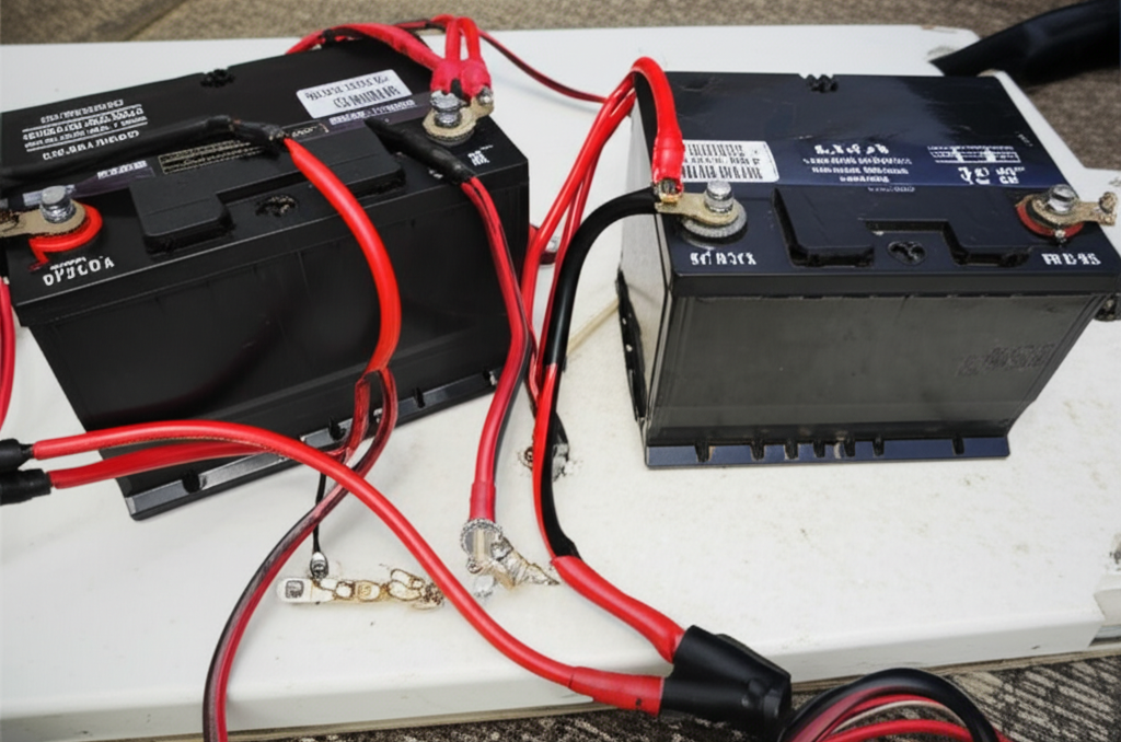
A 24-volt trolling motor uses two 12-volt deep cycle batteries connected in series. You do not need a single 24V battery. You create a 24-volt system by connecting the positive of one 12V battery to the negative of the other. The free negative on battery 1 and the free positive on battery 2 become your 24V output. That pairing gives the motor the voltage it expects. It does not double your amp-hours. Two 100 Ah 12V batteries in series create 24 volts at 100 Ah.
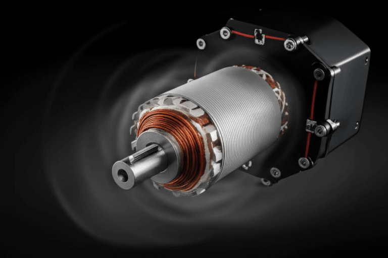
Understanding basic motor behavior helps. Higher voltage can deliver the same power with less current draw at a given speed setting. That lower current reduces heat and voltage drop in cables. If you want a quick refresher on how motors produce torque and spin with current and magnetic fields, this short explainer on the motor principle helps connect the dots.
Why 24V Beats 12V for Many Boats
I prefer 24V because:
- It provides more thrust for similar size motors.
- It draws less current for the same work at mid speeds.
- It runs cooler and feels more efficient.
- It leaves more headroom in rough conditions.
You don’t always need 36V. You can often solve performance and runtime issues by stepping from 12V to 24V with smart wiring and proper cable sizing.
Series vs Parallel: How to Connect Two 12V Batteries for 24V
- Series wiring combines voltage. Positive of battery 1 to negative of battery 2. The remaining free negative and free positive become your 24V output.
- Parallel wiring combines capacity at the same voltage. You would not use parallel for a 24V trolling motor because it keeps the system at 12V.
If you wire them in parallel by mistake, the motor will run as a 12V system. It will feel weak or not power up if the trolling motor expects 24V.
If you want an easy mental picture, I think of series like stacking two steps. Step one adds height. Step two adds more height. Parallel feels like widening the step without making it taller.
Essential Components and Tools I Rely On
Batteries: Lead-Acid, AGM, or Lithium
You need two 12-volt deep cycle marine batteries. Flooded lead-acid works fine if you maintain water levels and keep them charged. AGM batteries cost more. They offer lower internal resistance and better vibration tolerance. Lithium gives great weight savings, faster charging, and a flatter discharge curve. If you go lithium, make sure the trolling motor and battery management system are compatible with a 24V trolling motor battery bank setup. Check the manufacturer’s specs for max continuous discharge current. Many 24V motors can draw 50 to 70 amps at higher speeds.
Common phrases you’ll see in manuals:
- Deep cycle battery
- AGM battery 24V trolling motor wiring
- Lithium battery 24V trolling motor wiring
- Marine battery wiring for 24 volt trolling motor
Marine-Grade Wiring and the Right Wire Gauge
Use marine-grade, tinned copper cable with robust insulation. Ancor brand and similar marine-grade wire holds up to heat, moisture, and vibration. Fine-strand wire flexes better and resists fatigue. I size wire based on current and cable length to keep voltage drop under 3 percent. A 24v trolling motor wiring harness or custom-made cables with proper terminals make life easier. When in doubt, go one size larger. Voltage drop kills performance.
You’ll see these terms thrown around:
- Best wire gauge for 24v trolling motor
- What gauge wire for 50 amp 24v trolling motor
- Marine grade wiring 24v trolling motor
- Wire insulation types marine
Overcurrent Protection: Circuit Breaker vs Fuse
Install a marine-grade circuit breaker or fuse within 7 inches of the positive battery post when possible. Manufacturers like Minn Kota and MotorGuide often recommend a 60A breaker for 70 to 80 lb thrust motors. Some smaller 24V motors run a 50A device. Always check your manual.
Why a breaker:
- It protects against shorts and overloads.
- It’s easy to reset.
- It can double as a service disconnect.
Why a fuse:
- It costs less.
- It works well if sized and installed properly.
- You must carry spares.
Terms you’ll encounter:
- 24v trolling motor fuse size
- 24v trolling motor circuit breaker
- Selecting a circuit breaker for 24v trolling motor
- Proper fusing for 24v trolling motor
- Circuit protection standards
- Overcurrent protection
Connectors, Plugs, and Receptacles
I use ring terminals on battery posts and a trolling motor plug with a matching receptacle up at the bow or near the transom. Quick disconnect trolling motor system 24v setups make removal simple. Choose a receptacle with a waterproof cap and tinned contacts. Look for IP-rated marine connectors. Crimp with a proper tool and seal with adhesive-lined heat shrink connectors. I often dab dielectric grease on contacts to fight corrosion.
Useful pieces:
- Trolling motor plug and receptacle
- Waterproof connectors 24v trolling motor
- Female receptacle 24v trolling motor
- Male plug 24v trolling motor
- Wire terminals for 24v trolling motor
- Heat shrink connectors 24v trolling motor
Tools That Make the Job Easier
- Wire strippers and a quality crimping tool
- Heat gun for heat shrink tubing
- Multimeter for voltage checks
- Cable ties and adhesive mounts for cable management
- Battery boxes and battery hold downs
- A small torque wrench for battery terminals if you have one
Other helpful accessories:
- Battery tray for 24v trolling motor
- Terminal block or bus bar if you want tidy distribution
- Fuse holder if you choose fuses instead of a breaker
Planning and Preparation Before You Touch a Wire
Read the Manual
Start with the trolling motor manual. Every brand lists recommended breaker size, wire gauge, and special notes about wiring color coding or battery requirements. Minn Kota and MotorGuide share clear diagrams. I read the manual twice then lay out my gear. That habit prevents silly mistakes.
Battery Location, Battery Boxes, and Hold-Downs
Choose a stable spot low and centered if you can. Boats ride better with weight down low. Keep batteries in vented battery boxes with solid lids. Use proper battery hold downs so they cannot slide. I have seen a loose battery short across a metal strap when a wave hit hard. That will end your day fast. Battery tray options exist for most hulls.
Wire Routing and Cable Management
Plan your wire routing through hull spaces before you cut anything. Sharp edges and moving parts eat insulation. Use grommets where cables pass through bulkheads. Zip tie cables to keep them from flopping around. Secure the trolling motor power cable length so it can flex with the mount without snagging. On a bow mount, route the harness along the gunnel with cushion clamps or cable tie mounts. On a transom mount, follow the existing harness path and keep wires clear of the outboard tilt and steering.
Keywords that matter here:
- Wire routing for trolling motor
- Wire routing through hull
- Securing trolling motor wires
- Cable management 24v trolling motor
- Mounting trolling motor receptacle
- Front mount trolling motor wiring 24v
- Transom mount trolling motor wiring 24v
- Trolling motor bow mount wiring
Step-by-Step: Wiring Your 24V Trolling Motor
Step 1: Wire the Two 12V Batteries in Series
- Place Battery 1 and Battery 2 in their boxes and secure them.
- Connect a short jumper cable from the positive (+) terminal of Battery 1 to the negative (-) terminal of Battery 2. That link is the series jumper. This is the “how to connect 2 12v batteries for 24v trolling motor” step.
- The free negative (-) on Battery 1 and the free positive (+) on Battery 2 are now your 24V output points.
- Label those two posts for clarity. I add a small tag that says 24V negative on Battery 1 and 24V positive on Battery 2.
I like to sketch a quick “24v trolling motor wiring diagram” or print the manufacturer’s “electrical diagram 24v trolling motor” page. It helps prevent polarity mistakes. If you ever decide to re-wire, keep that diagram taped inside a hatch.
Step 2: Install the Circuit Breaker or Fuse
- Mount a marine-grade 50 to 60 amp circuit breaker close to the 24V positive terminal at Battery 2. Many motors at 70 to 80 lb thrust want a 60A breaker. Some smaller 24V models use 50A. Use the motor’s specs for the final call.
- Connect a short length of appropriately sized wire from Battery 2 positive to the input side of the breaker or fuse holder.
- Keep wire runs neat and supported. Aim for the shortest safe run to minimize voltage drop.
Common phrases:
- How to select a circuit breaker for 24v trolling motor
- Fuse protection for 24v trolling motor
- 24v trolling motor maximum amp draw
- What size fuse for 70lb thrust 24v trolling motor
Step 3: Wire the Trolling Motor Plug and Receptacle
- Run the main positive cable from the breaker output to the positive terminal of your trolling motor receptacle.
- Run the main negative cable from Battery 1 negative to the negative terminal of that receptacle.
- Crimp tinned copper ring terminals with a proper tool. Seal with adhesive-lined heat shrink tubing. I prefer heat shrink connectors for a waterproof seal.
- Mount the receptacle in a dry spot with a weather cap. Double-check the plug’s wiring instructions since some plugs swap colors.
Extra tips:
- Choose a receptacle rated for marine use with high amperage connectors.
- If you add a battery switch to isolate the trolling motor bank, install it on the positive side between the breaker and the receptacle. That’s the “how to wire a battery switch for 24v trolling motor” scenario.
- If you need an extension cable for 24v trolling motor runs, size it the same as your main leads.
Step 4: Final Connections to the Trolling Motor
- Plug the motor into the receptacle.
- Open the breaker to off. Confirm everything is secure.
- Close the breaker. Test the motor at low speed for a second.
- If it doesn’t power up, open the breaker and troubleshoot before trying again.
Before I power up a new install, I use a multimeter at the receptacle. I check for about 24 to 25.6 volts on fully charged lead-acid batteries. Lithium sits higher depending on its charge curve. That “how to check 24v trolling motor voltage” step saves surprises.
Step 5: Charging a 24V Battery Bank the Right Way
Use a two-bank marine charger with each bank connected to a separate 12V battery. It will charge each battery individually. That keeps the series wiring intact. You can also use a 24V charger designed for series banks. Follow the charger’s manual.
- 24v trolling motor battery charger connection
- 24v trolling motor battery charger wiring
- How to test 24v trolling motor batteries
Avoid mixing old and new batteries in a series pair. They age differently and drift in capacity. Replace them as a matched set when possible.
Wire Gauge, Voltage Drop, and Performance: The Deep Dive
Recommended Wire Size by Amps and Length
I aim for less than 3 percent voltage drop. It keeps thrust strong and helps the motor run cooler. As a rule of thumb for 24V systems using fine-strand marine-grade wire:
- 50 amps at 5 to 10 feet: 6 AWG
- 50 amps at 10 to 15 feet: 4 AWG
- 50 amps at 15 to 20 feet: 2 AWG
- 60 amps at 5 to 10 feet: 4 AWG
- 60 amps at 10 to 15 feet: 2 AWG
- 60 amps at 15 to 20 feet: 1 AWG
- 70 amps at 5 to 10 feet: 2 AWG
- 70 amps at 10 to 15 feet: 1 AWG
- 70 amps at 15 to 20 feet: 1/0 AWG
Those numbers line up with ABYC E-11 style guidance and common trolling motor manufacturer charts. Always check your motor manual. Use a reputable voltage drop calculator if your run is long or your deck layout is unusual.
You’ll hear these phrases in forums and manuals:
- Recommended wire size 24v trolling motor
- Voltage drop 24v trolling motor wiring
- What gauge wire for 50 amp 24v trolling motor
- Trolling motor power cable length
How Voltage Drop Hurts Thrust and Battery Life
I learned this the hard way on an older aluminum skiff. The bow run was long and the previous owner used undersized cable. The motor sounded anemic. New 2 AWG cable transformed it. That drop robs power. A 10 percent voltage drop can cost you a chunk of thrust and force higher current for the same speed. That makes wires hotter and drains batteries faster. Keep drop to 3 percent or less. Your motor will feel like it had a cup of coffee.
Safety Practices and Best Habits I Never Skip
- Always disconnect power before working. Open the breaker or remove the fuse. I also pull the plug from the receptacle.
- Use marine-grade wire and connectors. Automotive wire corrodes quickly on boats.
- Size wire and overcurrent protection correctly. Undersized wire is a fire hazard.
- Secure all wires to prevent chafing. Add grommets where cables pass through metal or fiberglass.
- Waterproof every connection with adhesive-lined heat shrink. Add dielectric grease to exposed terminals and plug contacts.
- Inspect twice a season for corrosion, loose fasteners, and chafing.
I also keep a small kit aboard:
- Spare fuses
- A short jumper wire
- A mini multimeter
- A few ring terminals and heat shrink sleeves
Corrosion is the silent killer. Salt spray and condensation creep into everything. I like tinned wire and sealed connections because they slow down the green crust that builds on bare copper.
A quick aside for the technically curious. Many motors use laminated steel in the stator and rotor to reduce eddy currents and heat. Better lamination design improves motor efficiency and smoothness. If you want to see how stators and rotors are put together, this overview of stator and rotor and deeper material on electrical steel laminations show why quality inside the motor matters even if you never open the case.
Troubleshooting: Fixing Common 24V Wiring Problems
No Power
- Check the breaker or fuse. Reset or replace as needed.
- Confirm the series jumper is in place from Battery 1 positive to Battery 2 negative.
- Measure voltage at the receptacle. You want around 24 volts.
- Inspect the plug for bent or corroded pins.
- Verify polarity. Reversed polarity can blow a fuse instantly.
Keywords that fit:
- Trolling motor not getting power
- Troubleshooting 24v trolling motor wiring
- Common wiring mistakes 24v trolling motor
Intermittent Power
- Wiggle test the plug while the motor runs at low speed. If it cuts in and out, replace the plug or receptacle.
- Check for poorly crimped connectors. Re-crimp with the right die and tool.
- Look for corrosion under heat shrink if it wasn’t adhesive-lined. Replace and reseal.
Terms to consider:
- Intermittent power
- Faulty plug
- Preventing corrosion trolling motor wiring
Weak or Sluggish Motor
- Measure voltage at the receptacle while the motor runs on high. A big drop hints at undersized wire or bad connections.
- Verify battery state of charge under load. One weak battery drags the system.
- Confirm wire gauge suits the run length and current.
- Inspect for heat at connections. Warm lugs indicate resistance.
You might search:
- Motor lacks power performance
- Voltage drop 24v trolling motor
- Incorrect wire gauge
Blown Fuse or Tripping Breaker
- Inspect for short circuits like pinched cables or exposed lugs contacting metal.
- Confirm the breaker size matches the motor spec. Undersized devices trip early.
- Test the motor alone with a short known-good cable to eliminate wiring as the culprit.
- If the motor trips instantly and wiring checks out, the motor could have an internal fault.
Useful phrases:
- Preventing short circuits 24v trolling motor
- Blown fuse tripping breaker
- Overcurrent protection
Quick Answers to Popular Questions
What size breaker or fuse do I need for a 24V trolling motor?
- Most 70 to 80 lb thrust 24V motors want a 60A circuit breaker. Some smaller models use 50A. Check your manual.
What gauge wire should I run for a 24V trolling motor at 50 amps?
- 6 AWG up to 10 feet. 4 AWG to 15 feet. 2 AWG to 20 feet. That follows my rule of keeping voltage drop under 3 percent.
How do I wire two 12V batteries for 24V?
- Positive of Battery 1 to negative of Battery 2 with a short jumper cable. The free negative on Battery 1 and the free positive on Battery 2 become your 24V output.
Do I need a trolling motor plug and receptacle?
- You don’t need one. I still install one because quick disconnects make service easy and keep connections clean.
Should I solder or crimp?
- Crimp with a high-quality tool and use adhesive-lined heat shrink. Solder-only joints can become brittle on a boat. Many marine techs avoid solder-only terminations for high vibration areas.
How do I waterproof connections?
- Use tinned copper terminals, adhesive-lined heat shrink, and a dab of dielectric grease. Choose waterproof connectors with good IP rating for exposed areas.
Can I extend the trolling motor wires?
- Yes. Use the same or larger gauge. Keep splices minimal and sealed. If you need a long run, consider a 24v trolling motor wiring harness made to length.
What about chargers for a 24V system?
- Use a two-bank 12V charger with each bank on each battery or a 24V charger designed for series banks. Follow the charger manual.
What about a battery switch?
- A battery switch can isolate the trolling motor bank. Wire it on the positive side between the breaker and the receptacle. Label everything clearly.
Does wire color matter?
- Red for positive and black or yellow for negative simplifies troubleshooting. Stick to marine conventions.
How often should I inspect the system?
- I inspect before each season and after any hard trip. Look for chafe, loose hardware, and corrosion.
A Few Real-World Tips That Save Time
- Use a label maker for both ends of every cable. You’ll thank yourself when you troubleshoot in the dark.
- Keep a laminated “24v minn kota wiring diagram” or “24v motor guide wiring” in the boat. It removes guesswork if someone else helps.
- If you mount the receptacle on the bow, orient the cap to shed water. Water finds every pin.
- If your run is near the maximum length for the wire size, step up a gauge. Voltage drop does not negotiate.
- Don’t stack too many ring terminals on one battery post. Use a bus bar or terminal block if needed to keep connections clean and tight.
- Avoid routing power cables next to sensitive sonar or transducer wires for long stretches. It can reduce interference on your screens.
A Quick Look Inside the Motor for the Curious
You do not have to understand motor internals to wire one well. It still helps to know why quality matters. Trolling motors rely on tight tolerances and carefully designed laminations in the stator and rotor to reduce losses and heat. Better laminations reduce eddy currents and improve efficiency which can translate to smoother thrust and longer runtime per charge. If you enjoy learning how those parts work, this primer on stator core lamination shows how the stationary portion shapes magnetic fields. This broader resource on electrical steel laminations covers the steels used in motors and transformers. You won’t open your motor on the dock. You’ll still appreciate why the internal build helps it run cool and quiet.
Putting It All Together: A Sample Wiring Walkthrough
Here’s how I wired a recent 24V bow mount with a quick disconnect and a 60A breaker:
- Two 12V AGM batteries in labeled boxes. Battery 1 aft. Battery 2 just forward of it. Short jumper between Battery 1 positive and Battery 2 negative.
- 2 AWG marine-grade tinned cable for a 15-foot run to the bow receptacle. Ring terminals crimped with a hex die and sealed with adhesive-lined heat shrink.
- A 60A ignition-protected marine breaker mounted 6 inches from Battery 2 positive with a protective boot.
- Positive from breaker to the bow receptacle positive. Negative from Battery 1 negative to the receptacle negative. Both wires routed through flexible conduit and cushioned clamps every 16 to 18 inches.
- A marine-grade plug on the motor lead. A dust cap on the receptacle.
- A dual-bank charger mounted near the batteries. One bank on each battery with 10 AWG charging leads. Zip ties arranged so service loops remain but nothing can rub.
- Final test with a multimeter at the receptacle. 25.4V on fresh AGMs. The motor spun strong on speed 1. No heat at connections after a short run at higher speed.
If the motor ever feels weak, I check voltage at the receptacle under load first. I find problems faster by starting at the motor connection and working back to the batteries.
Common Phrases and How They Fit Your Project
- 24v trolling motor plug wiring: The plug and receptacle steps above
- 24 volt trolling motor installation guide: This entire walkthrough
- How to wire a 24v trolling motor on a boat: Plan, series, breaker, receptacle, test
- 24v trolling motor battery bank setup: Two 12V in series plus a proper charger
- Series wiring explained 24v: Positive to negative jumper between batteries
- Wire color coding trolling motor: Red positive and black or yellow negative
- Negative and positive terminals 24v: Battery 1 negative and Battery 2 positive become the output
- Ground wire for 24v trolling motor: Boats often avoid a hull ground for DC systems. You return negative back to the battery bank
- Marine wiring standards 24v and ABYC: Follow ABYC E-11 style practices for safe, reliable installs
- Soldering vs crimping for boat wires: Crimp and seal beats solder-only joints on boats
- IP rating for marine connectors: Higher IP means better protection against spray and dust
Final Thoughts: Make It Safe, Make It Reliable, Enjoy the Water
Wiring a 24-volt trolling motor is not complicated. It rewards patience and good habits. Use two 12V deep cycles in series. Size your wire to keep voltage drop under 3 percent. Install a marine-grade 50 to 60 amp breaker close to the battery. Crimp and seal every connection. Route and secure your cables like they matter because they do. Test with a meter and fix small issues before they grow teeth.
When you do it right, the motor jumps to life. You get crisp thrust and quiet control. You fish longer with fewer surprises. That’s the real point of all this wiring. More time on fish. Fewer gremlins on board.
If you want a quick refresher on how the spinning bits inside your motor create torque, this short primer on stator and rotor is a solid companion read. If you want to go deeper into material science and how lamination stacks reduce losses in motors, take a look at electrical steel laminations. You don’t need that knowledge to wire your boat. It still rounds out your understanding of why a well-built motor and a clean 24V supply make such a sweet team.
Happy rigging. Safe boating. Tight lines.