How to Wire a Single Phase Motor for Forward and Reverse Rotation: A Comprehensive Guide
Here is the comprehensive guide to wiring a single-phase motor for forward and reverse operation.
Over the years, I’ve spent countless hours in my workshop, tinkering with everything from old lathes to custom-built conveyor systems. One of the most common tasks I’ve run into is needing a single-phase motor to run both forwards and backwards. Whether it’s for a milling machine, a hoist, or a simple bench grinder, getting that bidirectional control is a game-changer. But I’ll be honest, the first time I tried it, I stared at a mess of wires and a confusing diagram, feeling completely lost.
I’ve learned a lot since then, sometimes the hard way. I’ve seen what happens when you skip a safety step or misidentify a wire—let’s just say a puff of smoke from a brand new capacitor is a smell you don’t forget. That’s why I put together this guide. I want to walk you through the process, step-by-step, just like I would if I were standing right there with you. We’ll cover everything from the basic theory to the nitty-gritty of wiring a drum switch or a set of contactors. My goal is to help you get this done safely, correctly, and with confidence.
Table of Contents
- 1. Understanding Single Phase Motors and Reversal Principles
- 2. Critical Safety Measures Before You Begin Wiring
- 3. Identifying Your Motor’s Windings and Terminals
- 4. Step-by-Step Wiring Methods for Forward/Reverse Control
- 4.1. Method 1: Manual Control Using a DPDT Drum Switch
- 4.2. Method 2: Automated Control with Relays or Contactors
- 4.3. Special Cases: Internally Reversible Motors
- 5. Verifying Connections and Testing Your Motor’s Rotation
- 6. Advanced Considerations & Best Practices
- Conclusion: Safely Mastering Single Phase Motor Reversal
- Frequently Asked Questions (FAQs)
1. Understanding Single Phase Motors and Reversal Principles
Before we touch a single wire, it’s really important to understand what’s happening inside that motor. Knowing the “why” makes the “how” a lot easier and safer.
1.1. What is a Single Phase Motor?
At its heart, a single-phase AC motor is the workhorse you find in homes, garages, and small workshops. It’s designed to run on the standard household power that comes out of your wall sockets. Unlike their big three-phase cousins used in heavy industry, these motors need a little trick to get started.
You’ll commonly run into a few types:
- Capacitor-Start Motors: These use a capacitor to give the motor an extra kick of torque to get it spinning. You’ll find them on applications like air compressors and large fans that need a strong start.
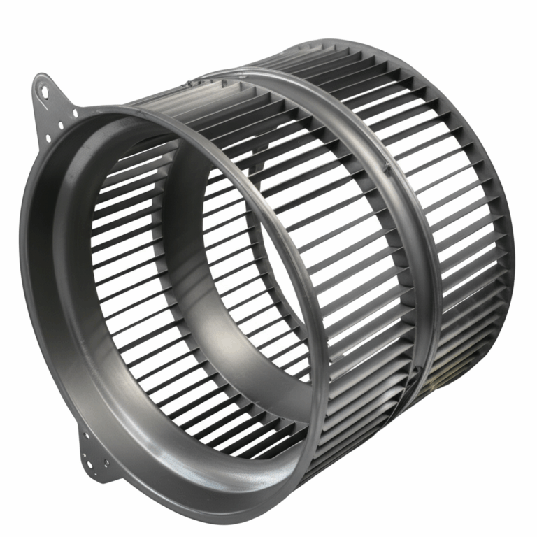
- Permanent Split Capacitor (PSC) Motors: These use a run capacitor that stays in the circuit the whole time. They’re quieter and more efficient, often used in blowers and appliances.
- Split-Phase Motors: This is a simpler design without a capacitor. They have lower starting torque and are usually found on smaller tools like bench grinders or small fans.
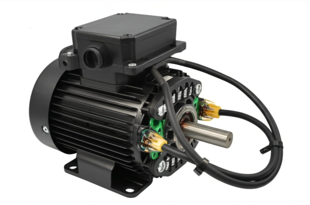
No matter the type, the core components are similar. You have the stationary part, the stator, which contains the electrical windings, and the rotating part, the rotor. The interaction between the magnetic fields of the stator and rotor is what creates the motion. The quality of the components inside, like the motor core laminations, directly affects the motor’s efficiency and lifespan.
1.2. The Core Principle of Reversing Rotation
So, how do we make it spin the other way? It’s simpler than you might think.
A single-phase motor has two main sets of windings wrapped around its stator: the main winding (or run winding) and the auxiliary winding (or start winding). The main winding does the heavy lifting once the motor is up to speed. The auxiliary winding is used primarily to create a second, out-of-phase magnetic field that “pushes” the rotor to start spinning in a specific direction.
Here’s the secret: To reverse the motor’s direction, you simply reverse the polarity of the start winding in relation to the main winding. That’s it. By flipping the connections to the start winding, you flip the direction of its magnetic field, which in turn gives the rotor a push in the opposite direction. The main winding connections stay exactly the same.
1.3. Key Motor Components for Reversal
When you open up the motor’s wiring box (also called a junction box), you’ll need to identify a few key parts:
- Main (Run) Winding: The set of wires that will remain connected the same way for both forward and reverse.
- Auxiliary (Start) Winding: The set of wires whose connections you will swap to change direction.
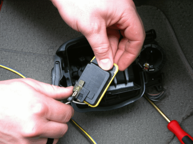
- Capacitor(s): You might see a start capacitor (often a black, plastic-cased cylinder) or a run capacitor (usually in a metal can), or sometimes both. These are wired in series with the start winding.
- Centrifugal Switch: In capacitor-start and split-phase motors, this mechanical switch is mounted on the motor shaft. Its job is to disconnect the start winding and start capacitor from the circuit once the motor gets up to about 75% of its full speed. If this switch fails, it can quickly burn out the start winding.
Understanding these parts is the first step to confidently rewiring your motor.
2. Critical Safety Measures Before You Begin Wiring
Alright, let’s talk about the most important part of this whole process: safety. I can’t stress this enough. Working with electricity, especially motor-level voltages like 120V or 240V, is no joke. I’ve heard too many stories of people getting a nasty shock or frying their equipment because they rushed. Let’s not be one of them.
2.1. Power Disconnection: The Golden Rule (Lockout/Tagout Procedures)
Before you even think about touching a wire, kill the power. This doesn’t mean just flipping a switch. You need to go to the circuit breaker panel and turn off the breaker that supplies power to the motor circuit. If it’s a plug-in motor, unplug it from the wall.
For a permanent installation, use a lockout/tagout (LOTO) procedure. This means putting a physical lock on the breaker so no one can accidentally turn it back on while you’re working. Trust me, it’s a simple step that prevents countless accidents in industrial settings, and it’s a great practice for the home workshop too.
2.2. Verifying Motor and Power Supply Ratings
Check the motor’s nameplate. This little metal tag is your best friend. It tells you the voltage (e.g., 115V/230V), full-load amps (FLA), horsepower (HP), and RPM. Make sure the voltage of your power supply matches the motor’s requirements. Wiring a 120V motor to a 240V circuit is a quick way to let the magic smoke out, and once it’s out, you can’t put it back in.
2.3. Essential Personal Protective Equipment (PPE)
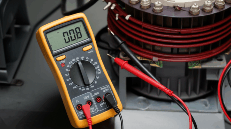
At a minimum, you should be wearing safety glasses. You never know when a stray wire spring might pop loose. If you’re working in a dusty or grimy environment, a pair of work gloves is also a good idea. For a final safety check, I always use a non-contact voltage tester to wave over the wires after I’ve shut off the breaker, just to be 100% sure the circuit is dead.
2.4. Adhering to Electrical Codes (NEC, local regulations) and Best Practices
While you might not be a professional electrician, following basic best practices is crucial. This means using the correct wire gauge for the motor’s amperage, making sure all connections are tight and secure inside an approved junction box, and properly grounding the motor frame. These rules exist to prevent fires and ensure safety.
2.5. Recommended Tools
Having the right tools makes the job easier and safer. Here’s my go-to list:
- Multimeter: Absolutely essential for identifying windings.
- Wire Strippers: For clean, proper stripping of insulation.
- Screwdrivers: Both flathead and Phillips head.
- Pliers: Needle-nose and linesman’s pliers are both useful.
- Voltage Tester: To double-check that the power is off.
3. Identifying Your Motor’s Windings and Terminals
Okay, with the power safely off, it’s time to play detective. The biggest hurdle for most people is figuring out which wires go where.
3.1. Deciphering the Motor Nameplate and Manufacturer’s Wiring Diagram
Your first stop should always be the motor’s nameplate or the wiring diagram, often found on a sticker inside the junction box cover. This is your treasure map. It will usually label the terminals (e.g., T1, T2, T3, T4, T5, T8) and show you exactly how to connect them for forward (often labeled CW for clockwise) and reverse (CCW for counter-clockwise) rotation. If you have this diagram, you’re golden.
3.2. Locating and Identifying Main (Run) and Auxiliary (Start) Windings
But what if the diagram is missing or unreadable? No problem. We can figure it out with a multimeter. Set your multimeter to the resistance (Ohms, Ω) setting.
- The main (run) winding will have a lower resistance value.
- The auxiliary (start) winding will have a higher resistance value.
For example, you might find that the wires labeled T1 and T4 have a resistance of 2 ohms, while the wires labeled T5 and T8 have a resistance of 5 ohms. In this case, T1-T4 is your main winding, and T5-T8 is your start winding. Write this down!
3.3. Identifying Capacitor Connections
If your motor has a capacitor, it will be wired in series with the start winding. The centrifugal switch is also part of this circuit. The diagram is the best way to confirm this, but generally, the start winding, capacitor, and centrifugal switch are all connected together to provide that initial starting torque.
3.4. Understanding Motor Terminal Block Markings
Manufacturers use standardized markings (like NEMA standards), but they can vary. Common markings are T1-T4 for the main winding and T5-T8 for the start winding. Sometimes you’ll see labels like P1 and P2 for thermal overload protectors. Always refer to the motor’s specific diagram if possible.
4. Step-by-Step Wiring Methods for Forward/Reverse Control
Now for the fun part. There are two main ways to wire your motor for forward and reverse control: a manual switch or an automated contactor setup.
4.1. Method 1: Manual Control Using a DPDT Drum Switch
For many workshop machines, a simple, rugged manual switch is all you need. The most common choice is a Double Pole, Double Throw (DPDT) switch, often in the form of a drum switch with a handle you can move to “FWD,” “OFF,” and “REV.”
4.1.1. How a DPDT Drum Switch Achieves Motor Reversal
A DPDT switch is perfect because it allows us to swap two connections simultaneously. Think of it as two separate light switches controlled by one handle. We’ll use it to flip the polarity of the start winding while leaving the main winding untouched.
4.1.2. Wiring Diagram: Single Phase Motor with DPDT Drum Switch
(Imagine a clear, simple diagram here showing the power lines, the DPDT switch, and the motor windings. Lines for the main winding go straight through, while lines for the start winding are cross-connected on the switch terminals.)
4.1.3. Step-by-Step Wiring Instructions for a Drum Switch
Let’s assume you’ve identified your windings: T1-T4 (Main) and T5-T8 (Start).
When you throw the switch one way, T5 connects to one line and T8 to the other. When you throw it the other way, the crossed jumpers reverse the connections, sending power to T8 and T5 in the opposite polarity. Voila! Reversing rotation.
4.1.4. Advantages and Limitations of Drum Switch Control
Advantages: Simple, cheap, and very reliable for manual operation.
Limitations: Not suitable for remote or automated control. It also lacks built-in safety features like preventing a change of direction while the motor is running at full speed, which can damage the motor or the machinery it’s driving.
4.2. Method 2: Automated Control with Relays or Contactors
For more advanced applications where you need push-button control or integration with a larger system, a contactor-based reversing starter is the professional choice. It’s more complex but also much safer and more versatile.
4.2.1. Introduction to Forward and Reverse Contactor Pairs
This setup uses two separate contactors (heavy-duty relays): one for forward and one for reverse. Each contactor is an electrically operated switch. When the “Forward” push button is pressed, it energizes the coil of the forward contactor, which closes its contacts and runs the motor. The “Reverse” button does the same for the reverse contactor.
4.2.2. Wiring Diagram: Single Phase Motor with Contactor-Based Reversing Circuit
(Imagine a more complex diagram here, showing two distinct parts: a high-voltage power circuit with two contactors and an overload relay, and a low-voltage control circuit with start/stop buttons and interlocking contacts.)
4.2.3. Step-by-Step Wiring Instructions for a Contactor Reversing Circuit
The wiring here is a bit more involved, but the principle is the same.
4.2.4. The Importance of Mechanical and Electrical Interlocks for Safety
This is the single most critical feature of a contactor setup. You can never have both the forward and reverse contactors energized at the same time. Doing so would create a dead short across your power lines, resulting in a loud bang, tripped breakers, and likely destroyed contactors. Industry data shows that a significant number of control panel failures stem from a lack of proper interlocking.
- Electrical Interlock: We use normally-closed auxiliary contacts from each contactor in the coil circuit of the other contactor. So, the reverse push button can only energize the reverse coil if the forward contactor is not engaged (and vice-versa).
- Mechanical Interlock: This is a physical lever or bar that sits between the two contactors. It mechanically prevents one from closing if the other is already closed. Always use both!
4.2.5. Advantages and Applications of Contactor Control
This method is perfect for conveyors, hoists, and any machine that needs remote or automated control. It’s safer, more robust, and the standard for industrial motor wiring.
4.3. Special Cases: Internally Reversible Motors
Some modern motors are designed for easy reversal. They might have extra wires coming out (e.g., a yellow and a purple wire) that you simply swap to change direction. Always check the motor’s diagram first—it might be simpler than you think!
5. Verifying Connections and Testing Your Motor’s Rotation
You’ve done the wiring. Now it’s time for the moment of truth. But don’t just flip the switch and hope for the best.
5.1. Double-Checking All Wiring Connections
Go back and check every single connection. Are the screws tight? Is there any exposed copper that could short against the motor casing or another terminal? I once spent an hour troubleshooting a motor that wouldn’t start, only to find a single loose connection on a terminal screw.
5.2. Performing an Initial, Brief Power-Up Test
This is called “bumping” the motor. Stand clear of any moving parts, turn on the power, and quickly flick the switch to “Forward” for just a second, then turn it off. The motor should jump and start to turn. Do the same for “Reverse.” This quick test confirms your connections are basically correct without letting the motor get up to full speed.
5.3. Safely Confirming the Direction of Rotation
If the bump test was successful, you can now do a full power-on test. Turn it on in the forward direction and confirm the shaft is spinning the way you expect. Then, let the motor come to a complete stop before testing the reverse direction. Never switch directly from forward to reverse while it’s spinning unless you have a specific motor and controller designed for that (which is rare for single-phase).
5.4. Common Troubleshooting Scenarios
If you encounter an issue, don’t panic. Dealing with a motor problem is common, especially on the first try. Here are a few things I’ve seen:
- Motor hums but won’t start: This often points to a problem in the start circuit. Check your start winding and capacitor connections. The centrifugal switch could also be stuck open.
- Motor runs in the same direction regardless of switch position: You’ve likely miswired the switch. Double-check that you’ve correctly crossed the connections for the start winding.
- Breaker trips immediately: This indicates a dead short. IMMEDIATELY DISCONNECT POWER. You most likely have a wiring error, especially in a contactor setup without proper interlocks. Re-check every connection against the diagram.
6. Advanced Considerations & Best Practices
To make your setup truly professional and durable, consider a few extra things.
6.1. Implementing Proper Motor Protection
A reversing starter isn’t complete without an overload relay. This device monitors the current the motor is drawing. If the motor gets jammed or overloaded, the current spikes, and the overload relay will trip, cutting power to the control circuit and saving your motor from burnout. It’s cheap insurance. Always size the overload relay according to the motor’s Full Load Amp (FLA) rating on the nameplate.
6.2. Ensuring Adequate Grounding for Safety
The motor’s metal frame must be connected to ground with a dedicated ground wire (usually green). This is a non-negotiable safety step. If an internal wire ever shorts to the frame, the ground wire provides a safe path for the fault current, tripping the breaker instead of electrifying the machine.
6.3. Correct Wire Sizing and Component Selection
Use a wire gauge that’s appropriate for the motor’s amperage and the length of the wire run. Using wire that’s too small is a serious fire hazard. Likewise, make sure your switches, contactors, and fuses or circuit breakers are rated for the motor’s voltage and horsepower.
6.4. Enclosures and Environmental Protection
All your wiring components—the switch, contactors, terminal blocks—should be housed in an appropriate electrical enclosure (like a NEMA-rated box) to protect them from dust, moisture, and accidental contact.
Conclusion: Safely Mastering Single Phase Motor Reversal
Wiring a single-phase motor for forward and reverse control might seem intimidating at first, but it breaks down into a logical process. By understanding the basic motor principle, prioritizing safety above all else, carefully identifying your components, and choosing the right control method for your needs, you can tackle this project with confidence.
I remember the satisfaction of flipping that drum switch for the first time and seeing my old drill press run in reverse. It opened up a new world of possibilities for tapping threads and backing out stuck bits. Whether you’re using a simple switch or a sophisticated contactor panel, the key is to be methodical, double-check your work, and never, ever work on a live circuit.
Frequently Asked Questions (FAQs)
Q: Can all single phase motors be reversed?
A: Most, but not all. The vast majority of capacitor-start, PSC, and split-phase motors can be reversed by swapping the start winding leads. However, shaded-pole motors (common in small fans) are generally not reversible unless they have been specifically designed with multiple windings for that purpose.
Q: What’s the main difference in reversing a capacitor-start vs. a PSC motor?
A: The principle is identical—you still reverse the start winding. The only difference is in the components. A capacitor-start motor also has a centrifugal switch in its start circuit that you need to account for, while a PSC motor’s start winding and run capacitor are always in the circuit. The wiring diagram will show you how they are connected.
Q: How do I identify start and run windings without a diagram?
A: Use a multimeter set to measure resistance (ohms). The start winding will always have a higher resistance reading than the run winding.
Q: Is it necessary to use a capacitor when reversing a single-phase motor?
A: If the motor was designed with a capacitor (like a capacitor-start or PSC motor), then yes, the capacitor is essential for the motor to operate correctly, regardless of direction. It must remain in the start winding circuit. You are only changing the polarity of that circuit, not removing its components.
Q: What are the risks of incorrect wiring?
A: The risks are significant. At best, the motor won’t run or will run in the wrong direction. At worst, you could cause a direct short circuit, leading to a fire, damage to the motor and control components, or a dangerous electric shock. Always double-check your work and prioritize safety.