Motor Core Laminations Made Simple: How to Cut Losses, Manage Cost, and Choose the Right Stack
Every design engineer faces the same tug-of-war. You need higher motor efficiency, cooler operation, and competitive cost. You also need a supplier who can hold tolerance and deliver consistent stacks without long lead times. If you are weighing lamination thickness, material grade, or whether to stamp or laser cut, you are in the right place.
This guide uses a Problem–Explain–Guide–Empower framework. We will frame the core design questions, explain the physics in plain language, compare practical options with trade-offs, then close with actionable steps you can take on your next project. I will also connect a common field complaint—“the HVAC fan only works on high”—back to motor current draw and lamination choices. It is a real-world reminder that materials and manufacturing decisions show up later as system behavior.
In This Article
- Why Lamination Material Choice Is Critical
- The Fundamentals: Eddy Currents, Hysteresis, and Permeability
- Material Considerations for Motor Laminations
- Manufacturing and Assembly Processes: What Changes in the Core Changes Your Motor
- Best Fit by Application: How to Choose for EV, BLDC, HVAC, and Transformers
- Side Note: Blower Motor Resistor vs Laminations—Why Diagnostics Often Point Back to Core Loss
- Quality, Standards, and Supplier Qualification
- Design Rules of Thumb That Save Iterations
- Cost Levers You Can Actually Control
- Your Engineering Takeaway and Next Steps
Why Lamination Material Choice Is Critical
Here is the problem in plain terms. Laminations set your core loss, your torque-per-amp, and your thermal margin. They also drive a surprising part of your final cost. Pick too thick a lamination or the wrong grade and you burn watts you never get back. Pick a process that leaves heavy burrs or damages coating and your stack factor falls along with performance. Overspec and you pay for capability you do not use.
You want a core that:
- Minimizes eddy current and hysteresis loss at your operating frequency.
- Reaches your target flux density without pushing into saturation.
- Holds tight geometry so your air gap is true and your slot shape does not wander.
- Assembles cleanly with a high stacking factor and robust mechanical integrity.
- Scales in volume without surprise unit cost.
That is a tall order. It is achievable with a clear view of the physics and the process.
The Fundamentals: Eddy Currents, Hysteresis, and Permeability
Let’s break the physics into simple pieces.
- Eddy currents: Think of unwanted whirlpools in a river. Changing magnetic fields induce circulating currents in conductive cores. Those currents churn heat and waste energy. Thinner, insulated laminations break the whirlpools into tiny swirls that die out fast. Eddy current loss scales with the square of lamination thickness and with frequency squared. Halve thickness and eddy loss drops roughly by four at the same frequency.
- Hysteresis loss: Imagine bending a paper clip back and forth. The metal resists the change then warms. Magnetic domains in steel act the same way when you cycle the field. The area inside the B–H curve is the cost per cycle. Lower coercivity (resistance to demagnetization) means less loss. Alloy composition and processing control this.
- Permeability: A higher relative permeability lets magnetic flux move through the steel like water through a sponge. You build the same torque with less magnetizing current. You also keep flux density below knee-of-the-curve saturation, which protects efficiency and avoids acoustic noise.
- Stacking factor: Insulation between laminations is necessary to block eddy currents. It also takes space. Stacking factor is the ratio of steel height to total stack height. High stacking factor means more active steel in the same slot length. Coatings and burr control drive this number.
- Frequency and waveform: Core loss is frequency dependent. A BLDC running with high PWM ripple produces high-frequency components that add to loss. A 50/60 Hz induction motor sees mostly fundamental loss. The same steel behaves differently in each case.
Quick mental model: At low frequency and modest flux density, hysteresis tends to dominate. As frequency rises or lamination thickness increases, eddy currents take the lead. You tune thickness and material grade to land the lowest total loss in your band.
A final word on voltage and current since many teams frame motor performance that way. Torque comes from air-gap flux and current. Excess core loss steals the thermal headroom that lets you push current during peaks. It also makes the motor look “heavier” electrically. You end up with higher current draw for a given torque output, which shows up as heat somewhere else in the system.
Material Considerations for Motor Laminations
You do not buy “steel.” You choose a grade and temper with a predictable B–H curve, core loss at defined flux densities, coating, and thickness. Here is a practical overview.
- Non-oriented silicon steels (NOES): This is bread-and-butter electrical steel for rotating machines. Common thicknesses are 0.35 mm, 0.3 mm, 0.27 mm, and thinner in premium grades. More silicon reduces loss and raises resistivity, which lowers eddy currents. It also reduces saturation flux density a bit. Use higher silicon content for higher frequency or when you are chasing fractional watts.
- Grain-oriented silicon steels (GOES): These shine in transformers where the flux aligns with the rolling direction. They are usually not used for rotating machines because flux rotates and would see poor performance off-axis. Keep GOES for transformer cores.
- Cobalt-iron alloys (e.g., 49–50% Co, often called Hiperco 50): These deliver high saturation flux density and good properties at higher frequency. You see them in aerospace machines, high speed drives, and magnetic bearings. They cost more. They also need careful processing.
- Nickel-iron alloys: In specialty sensors and actuators where very high permeability at low induction matters, NiFe can make sense. They are not common in mainstream motors due to cost and saturation limits.
- Amorphous and nanocrystalline alloys: Great for transformer cores at higher frequencies due to very low hysteresis and eddy losses. Adoption in rotating machines is limited by brittleness and manufacturing constraints. They continue to improve.
- Insulation coatings: The unsung hero. Coating class defines resistivity between laminations, temperature tolerance, and punchability. Poor coatings smear during stamping and wreck stacking factor. Choose coatings rated for your winding bake and operating temperature. Standards like ASTM A976 classify insulation types and relative performance.
The balancing act:
- Frequency rises. You favor thinner laminations and higher resistivity coatings.
- Flux density increases. You favor materials with higher saturation like cobalt alloys or carefully chosen NOES grades.
- Cost pressure dominates. You pick a common NOES grade and use geometry to limit loss.
- Acoustic targets tighten. You keep flux density off the knee and control slotting harmonics.
If you want a primer that spans the big picture, this overview of electrical steel laminations walks through properties and common applications at a component level.
Manufacturing and Assembly Processes: What Changes in the Core Changes Your Motor
Material gets you halfway. The process either preserves material properties or burns them away. Let’s compare the big knobs you can turn.
Stamping vs laser cutting vs EDM vs waterjet
- Progressive die stamping: The workhorse for volume. Highest throughput and best unit cost for large runs. You get predictable burr orientation, good repeatability, and tight tolerances once the die is dialed in. Upfront tooling cost is real. Burr height must be controlled to protect stacking factor. Edge stress can nudge losses upward if you push the limits. Most automotive stators and rotors use stamping.
- Laser cutting: Perfect for prototyping, pilot runs, or complex shapes with quick iteration. Heat-affected zones can degrade magnetic properties near the edge if you push speed without gas assist and thermal control. You can anneal to recover properties, which adds cost. Laser gives you freedom with small batch sizes.
- Wire EDM: Ultra-precise and no heat-affected zone. Slow and expensive. You will use it for test coupons or critical features you cannot compromise.
- Waterjet: No thermal damage. Cut quality and taper can be issues on thick stacks. It is unusual for production laminations in motors.
Burr control and stacking factor
- Burr height increases inter-lam spacing and can bridge insulation. You get lower stacking factor and potential eddy current paths. Specify burr limits and enforce them with incoming inspection and tool maintenance.
- Deburring steps add cost. Design your blank to reduce burr risk at critical edges. Consider grain direction relative to the punch.
Annealing and stress relief
- Mechanical processing introduces residual stress that raises hysteresis loss. For some materials and processes, a proper stress relief anneal restores magnetic properties. Your coating and the choice of bonding method must tolerate the anneal.
Bonding and assembly methods
- Interlocking: Tabs and notches snap laminations together like LEGO bricks. You get a rigid stack with no added adhesive. Local plastic deformation can add stress. It is fast and cost-effective at scale.
- Adhesive bonding: You build stacks with an epoxy or phenolic bonding film. It delivers high stacking factor and good mechanical integrity. You avoid interlock dimples in the magnetic path. You must control cure, squeeze-out, and cleanliness.
- Welding/brazing: Avoid in highly active magnetic areas. Heat can degrade properties and compromise insulation. Use sparingly in structural regions.
- Riveting and through-bolts: Mechanically simple. Plan rivet placement to minimize flux disturbance. It can work well for rotor back irons and yokes.
Tolerances and metrology
- Air gap concentricity moves your cogging torque and efficiency. Keep dies tight. Measure stacks for runout and flatness.
- Tooth tip and slot geometry drive winding fill and local flux density. You want consistency here or your iron loss model will miss.
If you want to dig into the components themselves, start with stator core lamination and rotor core lamination fundamentals. Geometry, tolerances, and joining choices differ by part.
Best Fit by Application: How to Choose for EV, BLDC, HVAC, and Transformers
One size does not fit all. Match the lamination strategy to the real electromagnetic and commercial constraints.
- EV traction motors
- Frequency: Electrical frequency can reach several hundred Hz at highway speeds. PWM switching adds high-frequency content.
- Material: Premium NOES at 0.27 mm or thinner is common. Some high-speed designs push thinner still.
- Process: Progressive stamping with tight burr control. Adhesive bonding or advanced interlocks for stiffness and NVH.
- Design: Skewed slots to reduce cogging torque. Bridges sized for burst speed. Rotor heat path matters.
- Industrial induction motors at 50/60 Hz
- Frequency: Mostly fundamental. PWM in VFD drives increases ripple loss.
- Material: Cost-optimized NOES like M19 variants at 0.35 mm often win. If VFD duty is aggressive, consider thinner stock.
- Process: Stamping with interlocking. Anneal if your loss targets and steel spec call for it.
- BLDC and PMSM in appliances and HVAC blowers
- Frequency: Anywhere from 50 Hz fundamental up to several kHz electrical in compact high-speed fans.
- Material: Thinner NOES reduces eddy loss. You may justify a premium coating for better interlam insulation at elevated temperatures.
- Process: Stamping for volume. Laser for prototypes and low volume variants. Adhesive bonding is common for noise and stacking factor.
- Note: For BLDC stators, tooth tips and back iron thickness drive both torque ripple and iron loss. If you build compact axial flux BLDCs, pay even closer attention to lamination thickness.
- Transformers
- If you are designing a transformer instead of a motor, consider transformer lamination core. GOES, EI and UI forms, and step-lap assemblies deliver low core loss when flux stays in the rolling direction.
- Specialty high-speed rotors
- If your surface speed and electrical frequency climb, cobalt iron can be worth it. It allows higher flux density at speed, which holds torque as you reduce turns for lower copper loss. You pay for it with material cost and processing care.
- Prototyping and pilot runs
- Laser cut thin NOES to develop your electromagnetic design fast. Validate loss on a single sheet tester then transition to stamping for production.
If you are focused on BLDC appliances or fans, you can skim a compact overview of a typical motor core laminations stack. It will help you map from CAD to manufacturable steel.
Side Note: Blower Motor Resistor vs Laminations—Why Diagnostics Often Point Back to Core Loss
You have likely heard this complaint from the field. “The car’s HVAC fan only works on high.” Or “the heater fan is intermittent.” Many technicians jump straight to the blower motor resistor because it is a common failure point. They are not wrong. The thermal fuse inside the resistor pack often opens. Yet the root cause sometimes sits inside the motor itself.
Here is the link to laminations. As the blower motor ages, bearing friction rises and windings warm. If the stator lamination stack has higher-than-expected core loss or poor stacking factor, the motor runs hotter at a given duty. Hot motors draw more current for the same airflow. That extra current flows through the resistor pack on lower speed settings, which means more heat at the resistor coils and the thermal fuse. Over time the thermal fuse opens. The fan still runs on “High” because the high-speed circuit often bypasses the resistor network. The resistor becomes the messenger who gets blamed.
If you maintain fleets or design HVAC modules, you should look at both sides: the resistor pack and the motor current draw. A quick test sequence helps you separate symptoms from causes.
- Visual check: Inspect the resistor pack for corrosion, melting at the connector, or broken coils. Check the wiring harness and connector pins for heat damage. Poor crimp quality or corrosion raises resistance and heat.
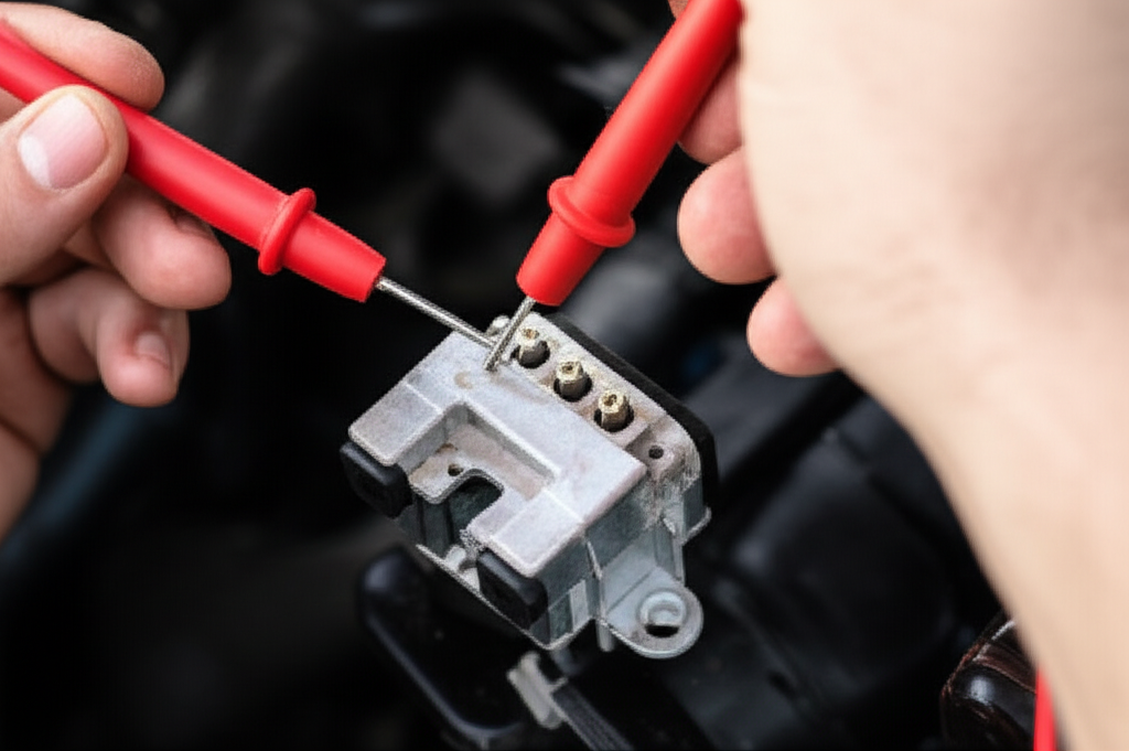
- Continuity and resistance checks: Use a digital multimeter. Measure continuity across each resistor path. Open circuit (OL) on a leg means a broken coil or blown thermal fuse. Expect low ohm readings on the functional legs. Values depend on the vehicle and speed step. Lower speed uses higher resistance.
- Voltage tests under load: With ignition on and the fan selector switching through speeds, measure voltage at the resistor input and output to the motor. You should see near battery voltage at input. Output voltage will vary with speed. Low speed outputs drop to a few volts at the motor due to the series resistor network. High speed should sit near battery voltage.
- Power and ground: Confirm solid ground at the resistor pack and blower motor. Any poor ground raises current draw and heat.
If the resistor checks bad, replace it and inspect the blower motor current draw. Compare the current at each speed to spec. A motor drawing more current than normal increases stress on the resistor pack. Sometimes the cure is a new motor and a fresh cabin filter to restore airflow. And if you design the motor, remember this loop. Lamination thickness, material grade, and assembly quality set your iron loss. Iron loss sets thermal headroom. Thermal headroom protects both the motor and the resistor pack downstream.
Relevant terms you will hear in these tests include Ohm’s Law, continuity, DC voltage, ground, open circuit, short circuit, voltage drop, and resistance check. They tie the electrical behavior back to the mechanical realities inside the motor core lamination stack.
Quality, Standards, and Supplier Qualification
Trust but verify. Good suppliers publish their process controls, material traceability, and test methods. Here is what matters.
- Material specifications
- ASTM A677 covers non-oriented electrical steel sheet and strip for magnetic applications. It defines properties and test methods.
- ASTM A976 classifies insulating coatings on electrical steels. It helps you match coating class to temperature and punchability.
- IEC 60404 series covers magnetic material test methods. IEC 60404-2 describes the Epstein frame for AC magnetic property measurement. IEC 60404-3 covers single sheet testers. IEC 60404-8-4 defines characteristics for high permeability and grain-oriented steels.
- If you buy GOES for transformers, ASTM A876 and related specifications apply.
- Test methods you should expect to see
- Core loss at specified induction and frequency using Epstein or single sheet tester.
- B–H curve characterization to extract permeability and coercivity.
- Stacking factor per ASTM A719. This tells you how much active steel you actually have.
- Burr height measurement and coating adhesion tests on sample blanks.
- Process control and documentation
- PPAP for automotive programs. You should see DFMEA, PFMEA, control plans, and dimensional capability studies.
- Lot traceability from heat number to finished stack. If you see a problem in the field, you need a fast path back to material and process data.
- Cleanliness and handling procedures to avoid coating damage and corrosion.
- Dimensional metrology
- Air gap critical dimensions with CMM checks. Tooth tip radius, slot width, and rotor OD matter for electromagnetic and mechanical performance.
- Flatness and runout checks on stacks. Ask how the supplier burns in their interlocks or bonds adhesive to control springback.
Ask for sample data. If a supplier hesitates to share standardized test results, proceed with caution.
Design Rules of Thumb That Save Iterations
You can cut design loops by leaning on a few robust heuristics. You will still need FEA and test data, yet these get you close fast.
- Choose lamination thickness via frequency
- 50/60 Hz: 0.35 mm is a solid starting point for many induction machines.
- 200–400 Hz: 0.3 mm or 0.27 mm reduces eddy loss with manageable cost.
- >1 kHz electrical or high PWM ripple: Consider 0.2 mm or thinner NOES, or evaluate specialty alloys if your budget allows.
- Set flux density below the knee
- For NOES, aim for peak flux density in teeth and back iron under 1.6–1.7 T for low acoustic noise and stable loss. You can push higher in bursts if thermal capacity allows.
- Do not starve the back iron
- Thin back iron saturates and forces more MMF from the windings. You waste copper and create hot spots. Let FEA tell you when you are close to the knee.
- Control slotting harmonics
- A slight skew or fractional slot combinations reduce cogging torque. The mechanical cost is small. Your acoustic team will thank you.
- Pay attention to bridges and ribs in rotor stacks
- They set burst speed and leakage. Too thick and you lose torque. Too thin and you lose sleep.
- Insulation coating counts
- Choose a coating that survives your winding bake, does not clog during punching, and maintains a high stacking factor. Ask for the coating class and target thickness.
- Validate core loss with test coupons
- Do not rely on catalog values alone. Cut coupons with your process parameters and measure. If you laser cut prototypes, consider a stress relief anneal or accept that the measured loss will be a bit higher than stamped production.
Cost Levers You Can Actually Control
You cannot wish market prices lower. You can squeeze cost by designing for manufacturing.
- Tooling amortization
- If you plan real volume, progressive die tooling pays back fast. Share your ramp forecast early so your supplier can spread cost sensibly.
- Nesting and scrap rate
- Small changes to OD, ID, and web thickness improve sheet utilization. Ask for a nesting study. It can shave several percent off material usage.
- Burr control without overprocessing
- Tight burr tolerances help, yet chasing zero burr with aggressive secondary operations burns time and money. Define burr where it matters then leave generous zones where it does not.
- Standardize lamination thickness across families
- Using one or two stock thicknesses across multiple motors unlocks volume pricing and shorter lead times.
- Bonding vs interlocking
- Adhesive bonding can boost stacking factor and reduce noise, which may let you drop a material grade or reduce lamination thickness. Run the math. The cheapest assembly method on paper is not always the lowest system cost.
- Measure twice, rework never
- Clear tolerance stacks that hit the air gap and winding envelope first. You can fight microns here or fight heat and noise later.
Your Engineering Takeaway and Next Steps
Here is the short list you can pin on your wall:
- Core loss comes from eddy currents and hysteresis. Thickness and alloy choice set the baseline.
- Frequency drives thickness. Higher frequency pushes you to thinner laminations and better coatings.
- Manufacturing can ruin great steel. Burrs, heat-affected zones, and poor bonding show up as loss and noise.
- Match the process to volume. Stamp production parts and laser cut prototypes. Anneal when needed.
- Validate with standards. Ask for IEC 60404 test data, stacking factor per ASTM A719, and coating class per ASTM A976.
- Design features like skew, bridge size, and back iron thickness often save more loss than exotic materials.
- Cost hides in scrap rates, burr control, and tooling choices.
If you are kicking off a BLDC, PMSM, or induction motor program, or you need a quick refresher on component-level options, browse stator core lamination, rotor core lamination, and this overview of motor core laminations for practical reference. For a broader material perspective, this page on electrical steel laminations offers a concise material summary you can share with your team.
Actionable next steps:
- Define your target operating frequency band and peak flux densities. This narrows material and thickness choices.
- Decide your prototyping and production mix. Pick laser cutting for early samples then lock stamping specs for production.
- Write a lamination specification that includes steel grade, thickness, coating class, burr limits, and required test data with standards called out.
- Schedule a design review with your lamination supplier. Bring your FEA outputs and tolerance stack. Ask for a nesting study and a proposal with at least two material options.
- Plan to test core loss early using single sheet or Epstein methods. Correlate results to your model.
When you drive clarity up front, you pull risk out of the build. You also set the stage for better efficiency and lower cost without drama.
References and standards:
- ASTM A677: Standard Specification for Nonoriented Electrical Steel, Fully Processed Types.
- ASTM A976: Standard Classification of Insulating Coatings by Composition, Relative Insulating Ability and Application.
- ASTM A719/A719M: Standard Test Method for Lamination Factor of Magnetic Materials.
- IEC 60404-2: Magnetic materials Part 2, Method of measurement of the magnetic properties of electrical steel sheet and strip by means of an Epstein frame.
- IEC 60404-3: Magnetic materials Part 3, Methods of measurement of the magnetic properties of electrical steel sheet and strip by means of a single sheet tester.
If you want a second set of eyes on your lamination stack or material choice, bring your frequency targets, torque-speed curve, and thermal limits. I will help you weigh the trade-offs and get to a clean, defensible decision.
Safe designing.