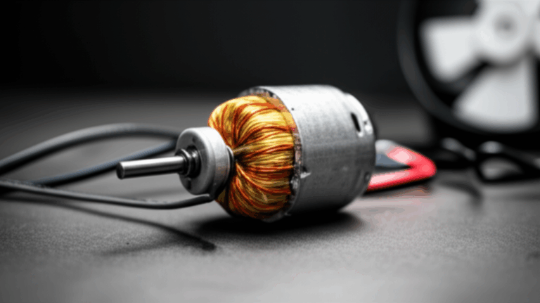
Motor Laminations 101: How to Choose Thickness, Material, and Process for Better Motors
Every design engineer runs into this sooner or later. The prototype runs hot. The efficiency targets feel just out of reach. Costs balloon when you shift from prototypes to production. You suspect the motor core is part of the story. You’re right. Lamination thickness, material grade, and assembly method quietly set the ceiling for motor efficiency, temperature rise, noise, and unit cost. Get them right and everything downstream gets easier. Get them wrong and you fight the motor from first sample to end of life.
This guide gives you a clear, practical path. We’ll break down the physics in plain language, lay out your material and process options without bias, then help you pick the right fit for your application. You’ll walk away with concrete selection rules, pitfalls to avoid, and the right questions to ask your lamination supplier.
In short, we’ll help you build confidence around motor laminations so you can design smarter and buy with intent.
In This Article
- The Problem You’re Solving: Efficiency, Heat, Cost, and Lead Time
- What’s Really Going On in Laminations? The Engineering Fundamentals
- Material Considerations: How to Choose the Right Electrical Steel
- Manufacturing and Assembly Processes: What Changes Performance and Cost
- Which Application Is This For? Best-Fit Choices by Use Case
- Design Tips You Can Use Today
- Compliance, Testing, and Documentation
- Your Engineering Takeaway
The Problem You’re Solving: Efficiency, Heat, Cost, and Lead Time
Let’s name the real trade-off. You need high efficiency and stable torque. You also need parts that scale cleanly to volume with consistent quality. On top of that you have a cost target and a tough schedule. Laminations sit right in the middle of that four-way tug-of-war.
- Thicker laminations cut steel cost and improve stacking factor. They also raise eddy current losses and heat.
- Thin laminations reduce core loss and improve high-frequency performance. They add cost and may slow throughput.
- Laser cutting gives you fast prototypes and complex geometry. It can introduce heat-affected edges that raise loss unless you anneal.
- Progressive stamping slashes piece price in volume. It demands expensive tooling and strong DFM discipline.
The good news. Clear design rules exist and they’re not hard to apply. The better news. A few smart choices early will save you headaches all the way through PPAP and production ramp.
What’s Really Going On in Laminations? The Engineering Fundamentals
Before we compare options, let’s ground the physics. You don’t need a PhD. You do need a mental model.
Magnetic flux, the B-H curve, and hysteresis
Magnetizing a core is like squeezing a sponge. Push the flux density B up and the material resists with its own internal stiffness described by the B-H curve. Two terms matter most:
- Permeability: how easily a material lets magnetic field lines pass. Think of it like how easily a sponge takes up water.
- Coercivity: the resistance to getting demagnetized. Lower coercivity means the material flips magnetization with less effort.
When you cycle the magnetization every electrical period, the core traces a loop on the B-H curve. That loop area is hysteresis loss. It becomes heat. Hysteresis scales mostly with frequency f and a material-dependent exponent on flux density B. Designers often treat it as proportional to f × B^n where n sits roughly between 1.6 and 2 for common grades.
Eddy currents: the unwanted whirlpools
Picture a river full of eddies behind a rock. In your core the changing magnetic field acts like that rock. It induces circulating currents in the steel. Those currents waste power as heat. Laminations slice the steel into thin sheets and add an insulating coating that breaks the loops. Thinner sheets → smaller loops → lower loss.
A useful rule of thumb: eddy current loss scales roughly with t^2 × f^2 × B^2. Halve the thickness and you cut that component by about 4x at the same flux and frequency. It’s the single most important reason to choose thin gauge stock for high-speed motors.
Core loss: the sum that drives temperature rise
Total core loss equals hysteresis loss plus eddy current loss. At 50/60 Hz hysteresis can dominate in many NOES grades. As frequency climbs the eddy term ramps fast. At a few hundred hertz and above eddy currents usually set the pace unless you move to very thin laminations or premium alloys.
Why you care. Core loss shows up as temperature rise. It steals efficiency. It can drive you into a bigger frame size just to shed the heat.
Saturation and flux density
Push B too high and the steel saturates. The permeability collapses and the magnetizing current spikes. Efficiency drops. Heat rises. You hear more acoustic noise. Keep peak flux below the material’s knee point with margin. That knee shifts with material grade and temperature.
A common pattern. Designers aim for 1.4–1.7 T in NOES for industrial motors at 50/60 Hz. High-frequency drives or premium materials pull that down to hold losses and noise in check. Treat these as starting points. Validate with your material’s datasheet and your motor test data.
Stacking factor and interlaminar insulation
The stack is not solid steel. You have sheet plus coating plus tiny air pockets. Stacking factor captures the ratio of steel thickness to total stack thickness. Higher stacking factor gives you more iron in the same axial length which boosts torque at a given flux density. Coating choice and lamination quality set this number. You also need high interlaminar resistance so the eddy currents stay small. That means good coatings, clean edges, and controlled burrs.
Material Considerations: How to Choose the Right Electrical Steel
Material choice sets loss, saturation, and cost before you cut the first tooth. You also lock in your coil requirements because copper loss must balance core loss if you want to hit efficiency targets.
You’ll choose among a few families of magnetic materials. Each has a sweet spot.
Non-oriented electrical steel (NOES)
This is the workhorse for rotating machines. It’s a silicon alloy steel that balances loss and permeability in all directions. You’ll see grades often labeled with “M” numbers in North America and different designations elsewhere. Lower “M” numbers generally mean lower core loss and higher price.
- Use NOES for induction motors, BLDC/PMSM stators and rotors, and most general-purpose rotating machines.
- Pick thinner gauges and higher grade for higher electrical frequency.
- Watch mechanical strength and stiffness when you push thin gauges. The lamination can wrinkle or deform during handling if the process isn’t dialed in.
If you need a primer on materials and their role in magnetics, this overview of electrical steel laminations is a helpful place to start.
Grain-oriented electrical steel (GOES)
GOES shines in transformers where flux runs mostly along one direction in the rolling plane. Motors see flux rotating, so NOES does better overall in rotating machines. GOES can still show up in special cases like certain synchronous reluctance designs with very directional flux. For most motors stick with NOES.
High-silicon low-loss NOES
Thin-gauge NOES with higher silicon content delivers lower loss at higher frequencies. You’ll pay more and accept tighter handling windows. It’s a strong choice for high-speed motors, compact BLDCs, and aerospace applications where every watt of loss matters.
Cobalt-iron alloys
Cobalt-iron stands out for very high saturation flux density and strong permeability at high frequency. It also costs far more and can be harder to machine. Consider it when you need high power density in tight spaces or when you must push flux density without saturating the core. Aerospace actuators and turbo machinery are typical candidates.
Amorphous and nanocrystalline materials
These alloys deliver extremely low core loss at high frequencies due to their microstructure. You’ll see them in high-frequency transformers and some specialized motor topologies. They can be brittle and tricky to process into complex lamination shapes. If you need very low loss beyond a kilohertz electrical, they deserve a look.
Coatings and insulation classes
Insulation coatings serve two jobs. They raise interlaminar resistance to break up eddy currents. They also affect stacking factor and withstand temperature during anneal and motor operation.
- Organic coatings give you good punchability and low cost. Temperature limits can be lower.
- Inorganic or hybrid coatings tolerate higher temperatures and can include “tension” coatings that lower magnetostriction which can reduce noise.
- Thicker coatings lower eddy current coupling but reduce stacking factor. Strike a balance based on your frequency and thermal class needs.
- Validate coating compatibility with your bonding adhesive or varnish. Some combinations don’t play well.
Ask your supplier for coating class, thermal rating, and interlaminar resistance data. Then confirm on parts after your selected process.
How to pick thickness by frequency
As a starting point:
- 50/60 Hz industrial motors: 0.5 mm to 0.35 mm works in many cases. Thinner reduces eddy loss if you can justify the cost.
- 200–400 Hz electrical (think 6–12 krpm on 2-pole machines): 0.35 mm to 0.27 mm moves the needle.
- 400–1000 Hz electrical and above: 0.2 mm to 0.1 mm or thinner becomes attractive. You’ll need careful handling and premium process control.
Treat these as guide rails. Use your material’s datasheet and your measured core loss to tune.
Manufacturing and Assembly Processes: What Changes Performance and Cost
The method you choose to cut, stack, and join laminations shows up in loss, noise, and price. Prototypes favor flexibility. Production favors repeatability and throughput. You can bridge the two with a good plan.
Progressive die stamping
Stamping is the workhorse for volume. Progressive dies feed strip material through multiple stations that blank, pierce, and form features in sequence. You get high speed and low piece price once the tool is debugged.
Pros:
- Fast cycle times and low unit cost in volume.
- Stable tolerances and repeatability.
- Designed-in features like interlocks, burr control, and skew segments.
Cons:
- High upfront tooling cost and lead time.
- Die maintenance and repair must be part of your plan.
- Burrs and work hardening can raise core loss if you push material or tool life too far.
Design for stamping early. Avoid fragile webs, tiny bridges, and deep narrow slots that chew up die life. Place pilot holes and embrace radii that boost tool life. Then specify burr height limits with teeth that point away from flux paths when possible.
Laser cutting
Laser wins in prototyping and low volume runs. It also handles complex geometries and quick design changes without tooling. You pay with edge quality unless you mitigate it.
Pros:
- No tooling. Design changes cost little and move fast.
- Complex geometries and small features are possible.
- Great for pilot builds and custom motors.
Cons:
- Heat-affected zone can damage microstructure near the edge. Loss rises.
- Oxides from O2 cutting and recast layers reduce interlaminar resistance.
- You often need stress relief anneal to recover properties which adds cost and time.
Mitigation:
- Cut with nitrogen to reduce oxidation.
- Optimize parameters for minimal HAZ and recast.
- Plan a stress relief anneal per the material supplier’s recommendations after cutting and before stacking.
Laser can be the right answer through EVT and DVT. Hand off to stamping once geometry stabilizes if you plan to scale.
Wire EDM
Wire EDM offers excellent edge quality with minimal thermal damage. It cuts slow. It also costs more per piece. Use it when you need high precision on features that matter magnetically or when you validate a new design that needs clean edges for loss testing. You can also combine EDM for critical features and laser or stamping for the rest in some hybrid workflows.
Waterjet
Waterjet avoids HAZ entirely. It can introduce taper and rough edges that affect interlaminar resistance. It’s a niche choice for certain prototypes when you need no heat input and can accept cleanup or additional process steps.
Post-processing: stress relief anneal
Cutting introduces residual stress. That stress raises core loss and can shift dimensions. A stress relief anneal can recover magnetic properties. Follow your material supplier’s recommended cycles. Watch the coating’s thermal limit. Not every coating survives the anneal temperature you need.
Stack assembly methods
How you join laminations behaves like a hidden variable in noise, loss, and manufacturability.
- Interlocking: Tabs and slots formed in the lamination mechanically lock the stack. Think LEGO bricks snapping together. You get robust stacks with no adhesive cure step. You may see slight local increases in loss near the locks. It’s great for volume with stamping.
- Bonding: Adhesive or resin bonds laminations into a rigid stack. You get excellent interlaminar insulation and low noise since there’s no rattle. The cure process adds steps and time. Adhesive must match your thermal class and vibration profile.
- Welding: Spot or seam welding clamps stacks fast. Heat can damage local magnetic properties. Use sparingly or away from the active magnetic path. Many teams weld the OD or ends of stacks that also interlock or bond internally.
- Riveting/cleating: Mechanical fasteners hold stacks without heat. They add hardware and can interfere with flux if placed poorly.
Pay attention to skew. Skewing rotor or stator stacks can reduce cogging torque and torque ripple. It can also cut acoustic noise. It adds manufacturing complexity. Progressive dies can produce skewed segments that assemble into a helical stack. Bonding helps hold skew under load.
For a deeper dive into how the stator influences your design, see these examples of stator core lamination. To balance the picture, review the role of the rotor core lamination in torque density and noise.
Quality metrics to specify and check
- Burr height: Small burrs reduce shorting between laminations and loss at teeth. Keep burrs low and directional. Typical targets sit in the tens of microns for premium stacks. Agree on a measurement method and sampling plan.
- Interlaminar resistance: Validate on coated samples and on finished stacks. Cutting and handling can change it.
- Dimensional tolerances and concentricity: The air gap does the talking. Hold OD, ID, slot, and key features tight enough to preserve air gap uniformity.
- Stacking factor: Confirm early since it feeds into EM design. Coating and process change it.
- Core loss on sample stacks: Measure at your expected peak flux and frequency on real stacks. Material datasheets give you a baseline. The stack tells you the truth.
You can find an overview of complete motor core laminations to see how these quality levers come together in production cores.
Which Application Is This For? Best-Fit Choices by Use Case
Different applications reward different choices. Let’s map common needs to sensible defaults.
Industrial induction motors at 50/60 Hz
- Material: Mid to high grade NOES that meets your core loss targets at 50/60 Hz.
- Thickness: 0.5 mm to 0.35 mm. Thinner if you want incremental efficiency gains.
- Process: Progressive stamping with interlocks in volume. Laser for prototyping then transition.
- Assembly: Interlocks plus a few welds on the OD or end plates. Bonding if noise or vibration demands it.
- Design notes: Aim for moderate flux density to reduce hysteresis loss and noise. Control burrs at teeth to keep interlaminar resistance high.
BLDC/PMSM for appliances, tools, pumps
- Material: NOES in thinner gauges as electrical frequency climbs. Consider low-loss grades to limit temperature rise in compact frames.
- Thickness: 0.35 mm to 0.2 mm depending on speed and pole count.
- Process: Start with laser for quick iteration. Move to stamping when the design freezes. Bonding can pay off by lowering acoustic noise and torque ripple.
- Assembly: Bonded stator stacks often shine here. Skew helps if cogging or tonal noise shows up.
- Design notes: Tight tolerances on the air gap deliver more than heroic magnet upgrades. Check slot-pole combinations for cogging tendencies early.
You can browse a focused view of a BLDC stator core to see common feature sets and stacking approaches that serve this class of motors.
EV traction and high-speed aerospace machines
- Material: Thin-gauge premium NOES or cobalt-iron for very high power density. Validate cost and supply risk up front.
- Thickness: 0.2 mm to 0.1 mm or thinner for very high electrical frequencies.
- Process: Laser with N2 assist for development plus post-cut anneal. Plan to move to high-precision stamping with tight burr control. Bonding stacks helps with NVH and mechanical rigidity at speed.
- Assembly: Bonding as the main approach. Mechanical retention via shrink fits or housings designed for high g loads. Skew may be limited by rotor dynamics and magnetization requirements.
- Design notes: Core loss can dominate the thermal budget at speed. Every tenth of a millimeter in thickness and every micron of burr matters.
Synchronous reluctance and axial flux motors
- Material: Thin-gauge NOES with attention to directional flux paths in barriers and bridges.
- Process: Laser or EDM for complex flux barrier shapes. Transition to stamping once features stabilize.
- Assembly: Bonded stacks to keep noise and vibration under control given thin web features.
- Design notes: Flux concentration and leakage control drive performance. Manufacturing constraints set a hard limit on slot and bridge geometry.
Transformers and static magnetic devices
- Material: GOES for conventional power transformers. Amorphous for very low-loss high-frequency transformers.
- Thickness: Thin gauges that match frequency and magnetizing current targets.
- Process: Stamping or cut-core processes that align grains in the right direction.
- Assembly: Lapped joints and careful stacking to minimize air gaps.
If your project centers on transformers rather than rotating machines, these insights carry over. The material and processing logic remains the same even if flux paths look different.
Design Tips You Can Use Today
You can apply these right now. They’re practical. They save time and grief.
- Halve lamination thickness when eddy currents dominate. You’ll cut that loss component by roughly 4x at the same frequency and flux. Validate on stacks since coating and burrs matter.
- Don’t chase paper specs without stack tests. Supplier loss curves help you compare. They don’t include your burrs, locks, or heat history.
- Control burr direction. Point burrs away from the primary flux path if you can. You’ll hold interlaminar insulation longer in the real world.
- Specify interlaminar resistance and stacking factor on drawings. Then measure them on first articles.
- Avoid sharp inside corners on teeth and bridges. Add small radii that match your process limits. You’ll extend die life and reduce microcracking if you laser cut.
- Plan a stress relief anneal when you laser cut thin gauges. You’ll often see a measurable drop in core loss after the cycle.
- Use skew with intent. A small skew can knock down cogging and noise. It can also shave peak torque slightly. Run the numbers and test.
- Consider bonding if noise or torque ripple hurts your application. Rattle in interlocks can show up as tonal noise. Bonding quiets stacks and improves interlaminar insulation.
- Keep flux density modest if you fight heat. Lower B usually reduces both hysteresis and eddy losses which buys you thermal headroom.
- Define a clean path to volume. Pick laser for fast iteration. Freeze geometry then tee up the stamping die. Transfer learning quickly with shared gauges and GD&T.
A quick example. You have a six-pole PMSM that runs at 12 krpm. Electrical frequency sits at 600 Hz. You use 0.35 mm NOES and the stator runs hot. You move to 0.2 mm with a higher-grade coating and run a stress relief anneal. At the same flux density you expect eddy loss in the teeth to drop by roughly (0.2/0.35)^2 which is about 0.33x. You still pay hysteresis loss so total loss might drop by 40–55% depending on your material. Your measured temperature falls by 10–20°C in steady state after you adjust the drive slightly to keep torque constant. That’s a healthy return for a single design change.
A cost thought experiment. You plan 300 samples. Laser is cheaper and faster than a die. You plan 20,000 units per year for two years. Stamping will pay back the die cost quickly. If the die costs $80k and stamping saves you $2 per lamination stack over laser plus anneal, you break even at 40k stacks. You hit that in year two. Your finance team smiles because your learning curve held your margin.
Compliance, Testing, and Documentation
No one loves paperwork. You still need it. It proves your design works and your supplier can repeat it.
- Material certificates: Confirm chemical composition and magnetic properties from the mill. Keep batch traceability.
- Core loss testing: Test single sheets at several flux densities and frequencies on arrival. Then test finished stacks at your target operating points. The IEC 60404 series covers test methods for magnetic materials and test apparatus. Use it to align methods with suppliers and labs.
- Motor testing: Use established standards like IEEE Std 112 for polyphase motors when you characterize efficiency and losses. You want apples-to-apples data across design iterations and builds.
- Dimensional and geometric tolerances: Use ISO system of limits and fits and ISO 286 for general tolerances. Define what matters for the air gap then measure it regularly.
- Adhesive and insulation systems: If you bond stacks, confirm adhesives meet your thermal class and chemical compatibility. Product safety often relies on recognized insulation systems. UL 1446 covers these systems for many applications.
- Automotive programs: Fold laminations into your APQP flow. Document PFMEAs for stamping or laser processes. Define control plans for burr height, interlaminar resistance, and stack flatness. PPAP will go smoother because the data tells a coherent story.
This is where a capable supplier saves you time. Ask for their standard test menus, sample reports, and handling guidelines for thin gauges. Your incoming inspection will be faster and more focused.
Your Engineering Takeaway
If you only remember a few things, make it these:
- Thinner laminations crush eddy currents at higher electrical frequencies. The loss reduction scales with thickness squared.
- Material choice sets your loss floor and saturation ceiling. NOES covers most motors. Cobalt-iron serves high power density applications. Amorphous and nanocrystalline shine at very high frequencies.
- Manufacturing changes magnetic behavior. Laser introduces HAZ. Stamping introduces residual stress and burrs. Annealing and good process control pull you back toward datasheet performance.
- Assembly matters. Interlocks are robust and fast. Bonding delivers low noise and strong interlaminar insulation. Choose based on NVH, cost, and reliability goals.
- Test stacks at your operating points. Datasheets help you compare materials. Your stacks tell you the truth about your design.
Next steps you can take this week:
If you want a fast sanity check on your current approach, share a single-page summary with your lamination supplier. Include frequency, flux density range, target efficiency, and expected volume. A 20 minute technical review will often surface one or two changes that save you weeks.
Finally, remember that the stator and rotor act as a team. Small, thoughtful improvements in each part of the stack add up. Better material. Cleaner edges. Smarter assembly. You’ll feel the difference on the test bench and you’ll see it in your warranty curve.
Looking for more context on how full stacks come together from material through assembly, including examples of common geometries and stacking strategies? This overview of motor core laminations offers a concise tour that pairs well with the guidance above.