The Engineer’s Guide to Motor Lamination: Boosting Efficiency and Performance
As an engineer or product designer, you’re constantly balancing performance, cost, and reliability. When it comes to electric motors, transformers, and generators, one of the most critical—yet often overlooked—components dictating this balance is the lamination stack. Choosing the right material and manufacturing process for your motor laminations isn’t just a line item on a bill of materials; it’s a fundamental design decision that directly impacts efficiency, thermal performance, and the overall lifespan of your product.
If you’ve ever found yourself asking, “How thin do my laminations need to be?” or “Which steel grade is right for my high-frequency application?”, you’re in the right place. This guide is designed to demystify the science behind motor laminations, giving you the practical knowledge to make informed decisions and have more productive conversations with your manufacturing partners. We’ll break down the core engineering principles, explore the materials and methods at your disposal, and empower you to select the optimal solution for your next project.
In This Article
- Why Laminations are the Heart of Your Motor’s Performance
- Deconstructing Core Losses: The Battle Against Eddy Currents & Hysteresis
- A Practical Guide to Lamination Materials: From Silicon Steel to Cobalt Alloys
- Manufacturing Methods: How Your Core is Made Matters
- Choosing the Right Lamination for Your Application
- Your Engineering Takeaway: Key Decision Factors
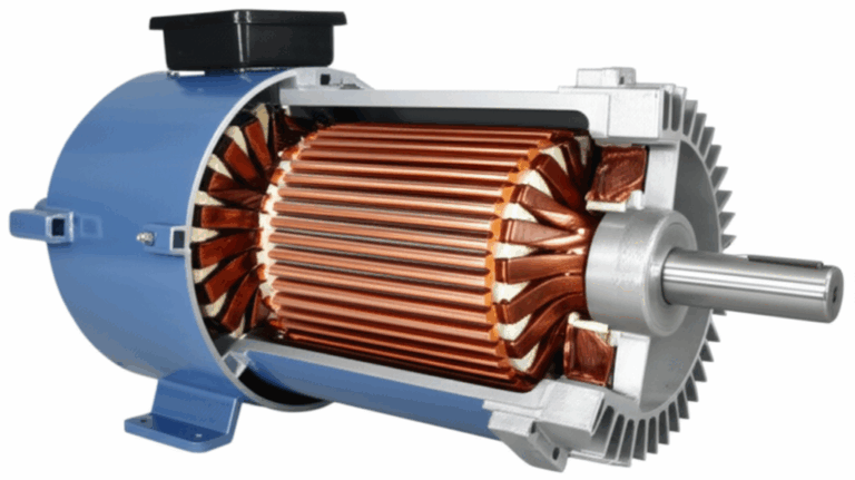
Why Laminations are the Heart of Your Motor’s Performance
At its core, an electric motor is a device that converts electrical energy into mechanical motion through the magic of magnetism. This process relies on a component called the core, which is made of a ferromagnetic material (usually an iron-based alloy) to concentrate and direct magnetic fields. You might wonder, “Why not just use a solid block of steel for the core? It would be simpler and stronger.”
The answer lies in an invisible enemy of efficiency: eddy currents.
When you apply an alternating current (AC) to a motor’s windings, you create a constantly changing magnetic field. This fluctuating field, in turn, induces small, circulating loops of electrical current within the motor’s core material itself. Think of them like tiny, unwanted whirlpools swirling in a river. These are eddy currents.
While they might be small, their collective effect is significant. They generate heat—a lot of it—through a process known as I²R loss (where I is current and R is resistance). This isn’t just wasted energy that lowers your motor’s efficiency; it’s also a major source of heat that can degrade insulation, damage bearings, and ultimately lead to premature motor failure.
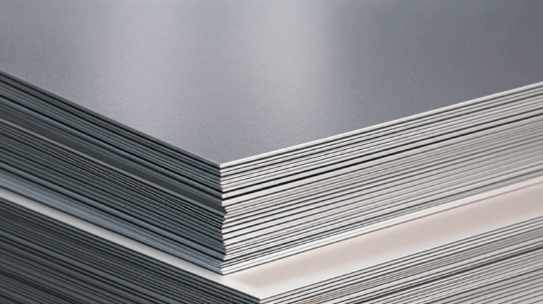
This is where laminations save the day. Instead of a solid core, we construct the core from a stack of very thin, electrically insulated sheets of metal.
Imagine that large, energy-wasting whirlpool in a solid core. Now, imagine placing hundreds of thin, parallel barriers in the water. The single large whirlpool can no longer form. Instead, you get hundreds of tiny, insignificant eddies between the barriers. The total energy lost is drastically reduced.
This is precisely how laminations work. By slicing the core into thin layers and insulating each one from the next (often with a thin oxide or organic coating), we dramatically increase the electrical resistance in the path of the eddy currents. This forces them into much smaller, less powerful loops, significantly cutting down on heat generation and energy loss. The thinner the lamination, the smaller the whirlpools, and the lower the eddy current losses—a crucial principle, especially in high-frequency applications.
Deconstructing Core Losses: The Battle Against Eddy Currents & Hysteresis
The total energy wasted as heat in a magnetic core is known as “core loss” or “iron loss.” Understanding its two main components is key to selecting the right material for your design.
1. Eddy Current Loss
As we just discussed, eddy current loss is generated by circulating currents within the lamination material. The magnitude of this loss is influenced by three primary factors:
- Lamination Thickness: This is the big one. Eddy current losses are proportional to the square of the lamination thickness. Halving the thickness of your laminations reduces eddy current losses by a factor of four. This is why high-frequency motors, which experience very rapid magnetic field changes, demand ultra-thin laminations.
- Frequency: Losses also increase with the square of the frequency. As motors spin faster or are driven by higher-frequency power electronics (like those in electric vehicles), managing eddy currents becomes paramount.
- Material Resistivity: A material with higher electrical resistivity will naturally restrict the flow of eddy currents. Adding silicon to iron, for example, significantly increases its resistivity, which is why electrical steel laminations are the industry standard.
2. Hysteresis Loss
The second piece of the core loss puzzle is hysteresis. To understand this, picture the magnetic domains within the steel as tiny, microscopic compass needles. When an external magnetic field is applied, these domains align themselves with it. As the AC cycle reverses, the magnetic field flips, and all those tiny domains have to flip around to realign.
This constant reorientation isn’t frictionless. It takes energy to overcome the internal “stickiness” or magnetic memory of the material. This energy is lost as heat with every cycle. Think of it like bending a paperclip back and forth—it gets warm because of the internal friction, and if you do it enough, it breaks. Hysteresis loss is that “internal friction” on a magnetic level.
The “loop” in the B-H curve (a graph of magnetic flux density B vs. magnetic field strength H) for a material represents this lost energy. A “fat” B-H loop means high hysteresis loss, while a “thin” loop indicates a more efficient material that realigns its magnetic domains with less effort. This property is largely determined by the material’s chemical composition and grain structure.
A Practical Guide to Lamination Materials: From Silicon Steel to Cobalt Alloys
The material you choose for your laminations is the foundation of your motor’s performance. The choice involves a trade-off between magnetic performance, mechanical strength, and cost.
Silicon Steels (Electrical Steels)
The workhorse of the motor and transformer industry. Adding silicon (typically up to 6.5%) to iron increases its electrical resistivity (fighting eddy currents) and reduces hysteresis loss.
- Non-Oriented Electrical Steel (CRNGO): This is the most common material for motor laminations. Its magnetic properties are uniform in all directions, making it ideal for rotating machinery like motors and generators where the magnetic flux path is constantly changing. You’ll find it in everything from industrial motors to household appliances.
- Cold-Rolled Grain-Oriented Electrical Steel (CRGO): In CRGO steel, the manufacturing process aligns the grain structure of the steel in a specific direction. This gives it superior magnetic properties (high permeability, low loss) only in that direction. Consequently, it’s the go-to choice for transformer lamination core applications, where the magnetic flux follows a well-defined path along the grain.
Cobalt-Iron Alloys (e.g., Hiperco®, VacoDur®)
When you need the absolute highest performance and power density, you turn to cobalt-iron alloys. These materials offer a significantly higher magnetic saturation point than silicon steels, meaning they can handle much stronger magnetic fields before becoming “full.”
- Pros: Exceptional magnetic performance, allowing for smaller, lighter, and more powerful motors. They also maintain their properties at higher temperatures.
- Cons: The primary drawback is cost—cobalt is an expensive element. They can also be more brittle and challenging to machine.
- Best For: Aerospace applications, high-performance electric vehicle racing motors, and specialized industrial equipment where size and weight are critical constraints.
Nickel-Iron Alloys (e.g., MuMetal®)
These alloys are known for their extremely high magnetic permeability, especially at low field strengths. Think of permeability as how easily a material can be magnetized. A high-permeability material acts like a “superhighway” for magnetic flux lines.
- Pros: Unmatched permeability, excellent for shielding sensitive electronics from magnetic fields.
- Cons: Lower saturation point than steels, meaning they can’t handle very strong fields. They are also more expensive.
- Best For: Sensitive instrumentation, magnetic shielding, and specialized transformers where precise control of low-level magnetic fields is required.
Amorphous & Nanocrystalline Metals
These are the new kids on the block. Instead of a crystalline grain structure, they have a random, glass-like atomic structure. This unique structure results in extremely low hysteresis losses, making them champions of high-frequency efficiency.
- Pros: Very low core losses, especially at frequencies above a few kilohertz.
- Cons: They are brittle, making them difficult to stamp, and they have a lower saturation point than silicon steels. They are also more expensive.
- Best For: High-frequency transformers, chokes, and specialized high-speed motors where minimizing core loss is the absolute top priority.
Manufacturing Methods: How Your Core is Made Matters
Choosing the right material is only half the battle. How you cut and assemble the laminations can have a significant impact on both cost and performance. The goal is to create precise shapes while minimizing stress and burrs, which can compromise the insulation between layers and increase losses.
Stamping (Punching)
This is the dominant method for high-volume production. A hydraulic or mechanical press uses a precision die to punch out the lamination shape from a coil of electrical steel.
- Pros: Extremely fast and cost-effective for large production runs. Once the tooling is made, the per-piece cost is very low.
- Cons: The initial cost of the die set (tooling) can be substantial, making it uneconomical for prototypes or small batches. Stamping also induces mechanical stress at the cut edge, which can slightly degrade magnetic properties.
Laser Cutting
Laser cutting uses a high-power, focused laser beam to melt or vaporize the material, creating a precise cut without any physical contact.
- Pros: No tooling costs, making it perfect for prototyping, R&D, and low-volume production. It can create highly complex geometries that are difficult or impossible to stamp. The heat-affected zone is very small, minimizing negative impacts on magnetic properties.
- Cons: Slower and more expensive on a per-piece basis than stamping, making it less suitable for mass production.
Core Assembly Techniques
Once the individual laminations are cut, they must be stacked and joined to form the final core. The chosen method affects the core’s rigidity, magnetic performance, and cost.
- Welding: A common method where beads are run along the outside of the stack. It’s fast and strong but can create localized hot spots that short-circuit the outer laminations, increasing eddy currents.
- Cleating or Riveting: Mechanical methods that clamp the stack together. These avoid the thermal issues of welding but can add to the stack’s overall dimensions.
- Interlocking: The laminations are stamped with small interlocking features (like tiny puzzle pieces) that snap together during stacking. This creates a strong, rigid core without the need for external fasteners or welding. It’s an excellent choice for maintaining magnetic integrity in components like the rotor core lamination.
- Bonding: The laminations are coated with an adhesive that cures under heat and pressure, essentially gluing the entire stack together. This creates the most rigid and uniform core, with excellent acoustic properties (less hum and vibration).
Choosing the Right Lamination for Your Application
So, how do you put all this information together? Let’s connect the dots for a few common scenarios.
- For a General-Purpose Industrial AC Motor: Here, cost-effectiveness is often the primary driver. A standard grade of non-oriented silicon steel (like M-19 or M-27) with a thickness of 0.50 mm or 0.65 mm, manufactured via stamping, is usually the best choice. This provides a good balance of performance and price for 50/60 Hz operation.
- For a High-Performance Electric Vehicle (EV) Motor: This application demands high efficiency across a wide range of speeds and frequencies. You would likely choose a very thin (e.g., 0.20 mm or 0.27 mm) high-grade non-oriented silicon steel. For top-tier performance where cost is less of a concern, a cobalt-iron alloy might be considered. The complex shape of the stator core lamination and rotor would probably be prototyped with laser cutting and then scaled to mass production with high-precision stamping.
- For a High-Frequency Power Supply Transformer: In this case, switching frequencies can be in the tens or hundreds of kilohertz. Here, eddy current and hysteresis losses would be enormous in traditional materials. This is a perfect application for amorphous or nanocrystalline materials to keep core losses and heat generation under control.
- For Rapid Prototyping and R&D: When you’re iterating on a design and need parts quickly without investing in tooling, laser cutting is the undeniable winner. It allows you to test different geometries and materials quickly and affordably before committing to a final design.
Your Engineering Takeaway: Key Decision Factors
Selecting the right lamination solution isn’t about finding a single “best” material, but about finding the optimal balance for your specific application. As you begin your next design, keep these key takeaways in mind:
- Frequency is King: The operating frequency of your device is the single most important factor. Higher frequencies demand thinner laminations and materials with lower core losses to manage heat and maintain efficiency.
- Performance vs. Cost: Be realistic about your requirements. While a cobalt-iron alloy offers incredible performance, a standard silicon steel may be more than sufficient and will save you considerable cost.
- Manufacturing Matters: Your production volume will heavily influence your choice of manufacturing process. Laser cutting is ideal for prototypes and small runs, while stamping is the clear choice for scaling to mass production.
- Consider the Whole System: The motor core is part of a larger system. How it’s assembled into core lamination stacks, its thermal management, and its interaction with the windings all contribute to the final performance.
Ultimately, the best designs come from a collaborative process. Don’t hesitate to engage with experienced lamination specialists early in your design cycle. Their expertise can help you navigate the material trade-offs and ensure your final product is efficient, reliable, and cost-effective.