Unveiling the Critical Role: What is the Function of a Centrifugal Switch in Single-Phase Motors?
If you’ve ever stood next to an air compressor, washing machine, or large workshop fan that hummed loudly for a moment before roaring to life, you’ve witnessed a critical engineering solution in action. That brief, powerful transition from standstill to full speed is often orchestrated by an unsung hero hidden deep inside the motor: the centrifugal switch. For any engineer, designer, or technician working with single-phase AC motors, understanding this component isn’t just academic—it’s fundamental to diagnosing problems, ensuring reliability, and designing efficient machinery.
You’re here because you need to know exactly what this switch does and why it’s so important. Perhaps you’re troubleshooting a motor that refuses to start, or maybe you’re designing a product and need to grasp the principles that drive your component choices. You’re in the right place. We’re going to demystify this clever electromechanical device, breaking down its purpose, mechanism, and critical role in the world of electric motors.
In This Article
- The Core Problem: Why Single-Phase Motors Need a Starting Boost
- The Centrifugal Switch: A Smart Starting Solution
- How Does a Centrifugal Switch Work? A Step-by-Step Breakdown
- Key Components of a Centrifugal Switch System
- Why is the Centrifugal Switch So Important?
- Where are Centrifugal Switches Found? Common Motor Types and Applications
- Common Issues and Troubleshooting a Centrifugal Switch
- Conclusion: The Unsung Hero of Single-Phase Motor Starts
The Core Problem: Why Single-Phase Motors Need a Starting Boost
Before we can appreciate the solution, we have to understand the problem. Unlike their three-phase counterparts which generate a naturally rotating magnetic field, single-phase induction motors have a fundamental challenge: they can’t start on their own.
Understanding Single-Phase Motor Starting Challenges
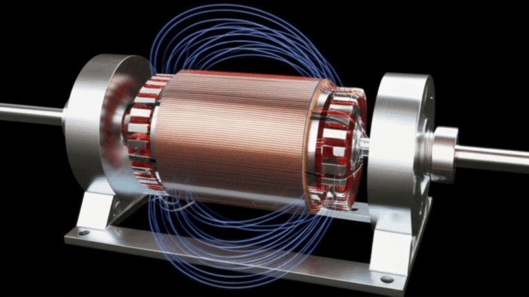
When you supply single-phase AC power to a motor’s main winding, it creates a magnetic field that simply pulses back and forth. It gets stronger, then weaker, then reverses polarity, over and over. Imagine trying to spin a merry-go-round by just pushing and pulling it along a single line instead of running in a circle. The merry-go-round will rock back and forth, but it will never start rotating.
This is precisely the situation inside a single-phase motor at a standstill. The pulsating field exerts a force on the rotor, but it’s equal in both clockwise and counter-clockwise directions. The rotor just sits there, humming under the strain, unable to decide which way to turn. This is where the engineering magic comes in. To get the motor spinning, we need to create a temporary “push” in a specific direction—we need to simulate a rotating magnetic field, just for a moment. This is achieved by adding a second, auxiliary winding, often called the “starting winding.”
The Centrifugal Switch: A Smart Starting Solution
The starting winding is the key to creating that initial rotational push. But leaving it energized after the motor is up to speed would be catastrophic. This is where the centrifugal switch takes center stage.
What is a Centrifugal Switch?
At its heart, a centrifugal switch is a speed-sensing electromechanical device. Think of it as an automated, mechanical brain for the motor’s startup sequence. Its one and only job is to connect the starting winding to the power source when the motor is stopped or running slowly, and then to completely disconnect it once the motor reaches a predetermined speed.
This simple function is absolutely vital. The switch ensures the motor gets the powerful starting torque it needs to overcome inertia and then transitions to its more efficient running state without destroying itself in the process.
How Does a Centrifugal Switch Work? A Step-by-Step Breakdown
The operation of a centrifugal switch is a beautiful blend of simple physics and electrical engineering. It’s a process that happens in a fraction of a second, but we can break it down into three distinct phases.
Phase 1: Motor Start-up (Switch Closed)
When the motor is off, the switch is in its “at-rest” position. A spring mechanism holds a set of electrical contacts firmly together, completing a circuit. The moment you flip the power on, electricity flows through two parallel paths: the main (running) winding and the auxiliary (starting) winding.
- The Circuit is Live: Because the centrifugal switch contacts are closed, the starting winding and its associated start capacitor (in capacitor-start motors) are energized.
- Creating the Push: The starting winding is designed differently from the main winding—it has different electrical properties (higher resistance, and often paired with a capacitor) that cause the current flowing through it to be out of phase with the current in the main winding. This phase difference creates the crucial, temporary rotating magnetic field.
- Torque and Acceleration: This rotating field gives the stator and rotor the strong directional push (starting torque) needed to begin spinning. The motor shaft starts to accelerate rapidly.
Phase 2: Speed Sensing and Disengagement (Switch Opens)
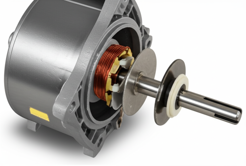
This is where the “centrifugal” part of the name comes into play. Mounted on the motor’s rotor shaft is a mechanical assembly with hinged weights.
- Centrifugal Force Builds: As the rotor spins faster and faster, centrifugal force pushes these weights outward, away from the shaft. Think of a figure skater pulling their arms in to spin faster and letting them out to slow down—it’s the same physical principle.
- Overcoming Spring Tension: The weights are held in place by a calibrated spring. At a specific speed—typically around 70-80% of the motor’s full rated speed—the outward centrifugal force on the weights becomes strong enough to overcome the inward pull of the spring.
- Opening the Circuit: As the weights fly outward, they act on a collar or plate that slides along the shaft. This movement physically pushes the movable contact away from the stationary contact, breaking the electrical connection. The starting winding circuit is now open. Click!
Phase 3: Running Operation (Switch Open)
With the starting winding and capacitor now completely out of the picture, the motor’s job isn’t over.
- Running on the Main Winding: The motor continues to accelerate and run using only its main winding. By this point, the rotor’s own momentum and the principles of induction are enough to keep it spinning efficiently under load. The pulsating field of the main winding is sufficient to sustain rotation, though it couldn’t initiate it.
- Protection and Efficiency: The starting winding is now safely de-energized, preventing it from drawing excessive current and overheating. The motor operates at its optimal efficiency, drawing only the power needed to drive the load.
When the motor is powered off, the rotor slows down, the centrifugal force diminishes, the spring pulls the weights back in, and the switch contacts close again, ready for the next start-up cycle.
Key Components of a Centrifugal Switch System
To fully appreciate how it works, let’s look at the parts that make up the system. They fall into two categories: the mechanical parts that sense the speed and the electrical parts that do the switching.
Mechanical Components
- Centrifugal Weights (Flyweights): These are the heart of the speed-sensing mechanism. As the motor shaft spins, these weights are thrown outward. Their mass and pivot point are carefully designed to act at a specific RPM.
- Spring Mechanism: This provides the counter-force to the weights. The spring’s tension is precisely calibrated to determine the “cut-out” speed. A weak spring would cause the switch to open too early, while an overly strong spring would cause it to open too late or not at all.
- Governor or Actuator Plate: This is the link between the moving weights and the electrical contacts. When the weights move, they push or pull this component, which in turn operates the switch.
Electrical Components
- Stationary Contacts: These are fixed points in the electrical circuit, typically mounted to the motor’s end bell or housing. One side is connected to the incoming power, the other to the starting winding.
- Movable Contacts: This part is physically moved by the actuator plate. When it presses against the stationary contacts, the circuit is closed. When it’s pulled away, the circuit opens.
- Connecting Wires: Simple but essential, these wires carry the current from the contacts to the starting winding and start capacitor.
Why is the Centrifugal Switch So Important?
So, what happens if this little device fails? The consequences can range from a motor that simply won’t start to a catastrophic burnout. Its importance can be boiled down to three key functions.
1. Preventing Overheating and Damage
This is arguably its most critical role. The starting winding is a sprinter, not a marathon runner. It’s built with thinner wire and is designed for very brief, intermittent duty—just a few seconds during startup.
If the centrifugal switch fails to open (e.g., the contacts get welded shut), the starting winding remains energized. It will continue to draw a very high current, far more than it can handle. Within seconds to minutes, the winding’s insulation will melt, causing a short circuit. You’ll often notice a distinct burning smell, followed by the motor tripping its thermal overload protector or circuit breaker. If left unchecked, this leads to permanent motor failure—a “burnout.” The cost of a new switch is dollars; the cost of a new motor can be hundreds or thousands, not to mention the operational downtime.
2. Enhancing Motor Efficiency
Motors are designed to be most efficient when running in their intended state. The starting circuit, with its high-current draw and reactive components like capacitors, is inherently inefficient for continuous operation. By disconnecting this entire auxiliary circuit, the centrifugal switch ensures the motor runs only on its highly efficient main winding. This minimizes I²R (heat) losses, optimizes the motor’s power factor, and reduces overall energy consumption during its operational life.
3. Ensuring Reliable Starting Torque
Conversely, if the switch fails to close when the motor is stopped (e.g., due to dirty or pitted contacts), the starting winding never gets energized. The motor receives power only to its main winding. The result? The dreaded hum. The motor has power but no directional push. It will sit there, locked in place, drawing a huge amount of current (known as locked-rotor amps) until a breaker trips or the main winding itself overheats and fails. The switch guarantees that the high-torque starting mechanism is engaged precisely when it’s needed most: at zero RPM.
Where are Centrifugal Switches Found? Common Motor Types and Applications
You won’t find a centrifugal switch in every single-phase motor. Modern electronics have led to alternatives like solid-state relays or PTC (Positive Temperature Coefficient) starters in some smaller applications. However, they remain incredibly common and reliable in two major types of induction motors.
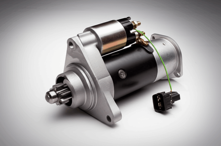
Capacitor-Start Induction Motors
These are workhorse motors that need high starting torque. They use a start capacitor in series with the starting winding to create a large phase shift, resulting in a powerful starting kick. The centrifugal switch is essential for disconnecting both the winding and the capacitor.
Split-Phase Induction Motors
These are generally lower-cost motors with more moderate starting torque. They don’t use a capacitor but rely solely on the different resistance/reactance properties of the two windings to create the phase shift. The function of the centrifugal switch remains identical: disconnect the starting winding once the motor is up to speed.
Typical Applications:
The need for high starting torque is common in machinery that has to start under load. You’ll find these motors everywhere:
- Appliances: Washing machines (to spin a heavy drum of wet clothes), clothes dryers, and refrigerators.
- HVAC Systems: Blower motors that need to move a large volume of air from a standstill.
- Workshop Equipment: Air compressors (starting against tank pressure), water pumps, large fans, and power tools like table saws and drill presses.
- Industrial Machinery: Conveyor belts, grinders, and various other machines requiring a robust single-phase power source.
Common Issues and Troubleshooting a Centrifugal Switch
Because it has both mechanical and electrical moving parts, the centrifugal switch is a common point of failure in older or heavily used motors. Understanding its function is the first step in diagnosing a potential motor problem.
Symptoms of a Faulty Switch:
- Motor Hums But Won’t Start: This is the classic symptom of a switch that has failed to close. The contacts might be dirty, corroded, or misaligned, preventing the starting winding from ever getting power. The motor is trying to go, but it has no initial push.
- Motor Starts, But Trips Breaker After a Few Seconds: This points to a switch that has failed to open. The contacts may have arced and welded themselves together, or the mechanical governor is stuck. The motor starts correctly, but because the starting winding remains engaged, it draws massive current, overheats almost instantly, and trips the thermal overload or circuit breaker. You might also hear a buzzing sound or smell burning insulation.
- Slow or Sluggish Starting: If the contacts are pitted or making a poor connection, the starting winding might receive some power, but not enough. This results in weak starting torque, causing the motor to struggle to get up to speed, especially under load.
Causes of Failure:
- Worn or Pitted Contacts: Every time the switch opens, a small electrical arc can occur, especially under load. Over thousands of cycles, this arcing erodes the contact surfaces, leading to a poor connection.
- Stuck Mechanism: Dust, dirt, grease, or rust can cause the weights or the actuator collar to become sticky or seized. If the weights can’t fly out, the switch won’t open. If they get stuck in the outward position, the switch won’t close upon shutdown.
- Broken Springs: The return spring can weaken over time or break, preventing the switch from closing properly when the motor stops.
Troubleshooting often involves visually inspecting the switch mechanism for free movement and checking the electrical contacts for continuity with a multimeter when the motor is off.
Conclusion: The Unsung Hero of Single-Phase Motor Starts
The centrifugal switch is a perfect example of a simple, robust solution to a complex engineering problem. Without it, the vast world of powerful single-phase motors that drive our homes, farms, and workshops wouldn’t be practical or reliable. While it may seem like a minor component, its function is anything but.
Let’s recap its vital contributions:
- It enables starting: It engages the auxiliary winding to create the rotating magnetic field necessary to overcome inertia.
- It protects the motor: By disconnecting the starting winding, it prevents catastrophic overheating and burnout.
- It optimizes efficiency: It ensures the motor runs on its main winding, saving energy and promoting a longer service life.
So, the next time you hear that momentary hum before a machine roars to life, you’ll know exactly what’s happening inside. It’s the sound of a centrifugal switch flawlessly performing its critical, split-second duty—the sound of a well-engineered start. Understanding this fundamental motor principle not only makes you a better technician or engineer but also gives you a deeper appreciation for the clever designs that power our world.