What Are 3 Phase Motors? Your Essential Guide to Industrial Powerhouses
Every design engineer faces the same thorny question at some point. How do you get more efficiency and reliability from a motor system without breaking the budget. If your application uses significant power and runs for long hours you will likely end up with a three-phase motor. The next question comes fast. What should you do about motor laminations to hit IE3 or IE4 efficiency and still keep manufacturing cost and lead time under control.
You are in the right place. This guide explains what three-phase motors are, why they dominate industry, and how the choice of lamination materials and manufacturing methods shapes real-world performance. We will keep the physics simple. We will point out trade-offs you can act on. You will walk away with a clear plan for design and procurement.
In This Article
- Why Three-Phase Motors Matter to Your Design and Budget
- Three-Phase Basics: How These Motors Turn Electricity Into Torque
- Inside the Motor: Stator, Rotor, and Laminations
- Understanding Core Losses: Eddy Currents and Hysteresis
- Types of Three-Phase Motors and Where They Fit
- Three-Phase vs Single-Phase: A Quick Comparison
- Material Choices for Laminations: Silicon Steel, Cobalt, and More
- Manufacturing and Assembly: Stamping, Laser, Bonding, and Quality Factors
- Power Electronics and Control: Star/Delta, VFDs, Starters, Protection
- Matching Solutions to Applications
- Specs That Matter: Ratings, Efficiency Classes, and Standards
- Practical Procurement Checklist and Next Steps
Why Three-Phase Motors Matter to Your Design and Budget
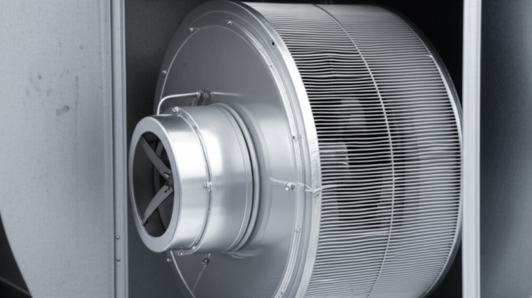
Three-phase motors are the unsung workhorses of modern industry. They run pumps, compressors, conveyors, fans, HVAC systems, machine tools, and countless automated lines. Most industrial facilities choose three-phase AC motors because they deliver more power for the same frame size, smoother torque, better efficiency, and simpler starting than single-phase motors. That means lower lifetime energy cost and higher uptime.
A few facts put the scale in perspective. Electric motors consume over half of the world’s electricity according to agencies like the IEA and DOE. The majority of that demand comes from three-phase AC motors. Upgrading to premium efficiency motors and coupling them with variable frequency drives can cut energy use dramatically in variable torque loads like pumps and fans. Many facilities see 20 to 50 percent energy savings when they match motor speed to demand instead of running full tilt all the time. That is not a rounding error. It is budget changing.
Efficiency standards tell the same story. IE3 and IE4 efficiency classes raise the bar by a few percentage points over standard motors which sounds small on paper. In a 24/7 operation those points translate into large electricity savings, lower operating temperatures, and longer insulation life. Engineering leaders do not chase these classes for bragging rights. They do it because the math works.
So where do laminations fit into this. Laminations set the ceiling for how efficient and quiet your motor can be. They limit core losses, shape magnetic flux, and affect noise and vibration. You control those outcomes through the grade and thickness of electrical steel, the integrity of the stator and rotor stacks, and the way you cut, insulate, and bond the laminations. We will unpack all of that in clear terms.
Three-Phase Basics: How These Motors Turn Electricity Into Torque
At its heart a three-phase motor is a machine that converts electrical energy into mechanical energy using three alternating currents that are 120 degrees out of phase with each other. Those three currents flow through the stator windings and create a rotating magnetic field. Imagine three people pushing a merry-go-round in sequence. No jerks. Just smooth rotation.
A few core ideas make the picture complete:
- Alternating Current (AC): The voltage and current change direction in a sine wave. Three-phase power uses three such sine waves spaced evenly at 120 degrees.
- Rotating Magnetic Field (RMF): The three-phase currents in the stator windings create a magnetic field that rotates around the stator at a speed set by the power frequency and the number of poles in the stator. Engineers call the ideal speed synchronous speed.
- Stator and Rotor: The stator is the stationary outer part with windings. The rotor is the rotating inner part connected to the shaft and bearings.
- Air Gap: A thin gap between stator and rotor. Too small and you risk contact. Too large and you lose efficiency because the magnetic circuit gets weaker.
How does torque appear. In an induction motor the rotating magnetic field induces currents in the rotor bars. Those currents interact with the stator field and produce torque. The rotor always turns a bit slower than the rotating field which engineers call slip. In a synchronous motor the rotor locks in step with the rotating field using permanent magnets or field windings so it spins exactly at synchronous speed. Both architectures benefit from the inherent smoothness of three-phase power which brings lower vibration and quieter operation.
The upshot. Three-phase power gives you balanced currents, lower conductor size for the same power, and smooth torque with minimal pulsation. You get better power factor, simpler starting, and less mechanical stress across your system.
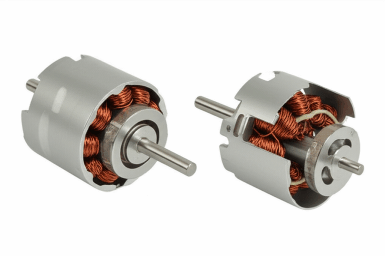
Inside the Motor: Stator, Rotor, and Laminations
Pop the end bells off a three-phase motor and you will see the same cast of characters in nearly every frame size and NEMA or IEC design.
- Stator: The stack of steel laminations with slots that hold the copper windings. The quality of the stator core lamination directly shapes efficiency because it controls the magnetic path and core losses.
- Rotor: Another stack of steel laminations mounted on the shaft. In a squirrel cage rotor, aluminum or copper bars run through the slots and short together at the ends with end rings. The consistency of the rotor core lamination affects torque ripple, losses, and noise.
- Windings: Copper conductors laid into the stator slots and connected into three phases in either delta or wye configuration.
- Shaft and Bearings: The rotor mounts on a steel shaft. Bearings support the shaft inside the end bells. Bearing selection and fits matter a great deal for noise and reliability.
- Frame and Housing: Protect the motor internals and help manage cooling. Typical enclosures include TEFC, TENV, and ODP depending on environment and airflow needs.
Why laminations. The stator and rotor cores are built from thin sheets of electrical steel that are insulated from each other. This is not cosmetic. These stacked laminations fight eddy currents and hysteresis losses which are the main sources of heat in the iron core. Thin laminations with good insulation coatings force those circulating currents to shrink which slashes heat and boosts efficiency. When engineers talk about IE3 or IE4 motors they often talk about lamination thickness, grade, and coating because those choices drive core loss more than any other single factor.
If you take one idea from this section take this. A motor is only as efficient as its magnetic circuit and that circuit lives inside the lamination stacks. Choose wisely and your design sings. Choose poorly and you bake watts into waste heat.
Understanding Core Losses: Eddy Currents and Hysteresis
Let’s break down the culprits that steal efficiency in your motor core. Two loss mechanisms do most of the damage.
- Eddy current loss: Think of eddy currents like small, unwanted whirlpools in a river. The changing magnetic field induces electrical currents in the steel core. Those currents swirl around and generate heat. Thin, insulated laminations act like boulders that break up big whirlpools into tiny eddies so they lose energy quickly. Thinner laminations mean smaller loops and lower eddy current loss. Loss rises roughly with the square of lamination thickness and with the square of frequency which matters a lot when you run on a VFD at higher switching frequencies or at higher fundamental frequency.
- Hysteresis loss: Magnetic domains in the steel flip direction every cycle as the field swings. That flipping takes energy which becomes heat. Materials with low coercivity and narrow B-H curves lose less energy each cycle. Silicon steel reduces hysteresis loss compared to plain carbon steel. Cobalt alloys can do even better at certain flux densities and temperatures but they cost far more.
A few more practical points for three-phase motor designers:
- Flux density and saturation: Run too high and you push steel into saturation which spikes loss and distorts current. Run too low and you carry extra steel weight for no benefit. Balance is key.
- Permeability and magnetic path: Permeability is how easily a material lets magnetic field lines pass. Think of high permeability like a sponge that soaks up water easily. Better permeability reduces magnetizing current and improves power factor.
- Insulation coating: Each lamination carries a thin inorganic or organic coating that provides interlaminar insulation. Coating class and bake cycles affect stacking factor, punchability, weldability, and corrosion resistance. The coating must survive VFD-induced voltage stress and temperature cycles without cracking or carbonizing.
- Frequency and harmonics: VFDs bring great control and big energy savings. They also add harmonics that increase core loss and cause additional heating. Use dv/dt filters or sine filters when needed. Check the insulation class and bearing protection for VFD duty.
- Mechanical noise and vibration: Electromagnetic forces ripple at slot and tooth passing frequencies. Skewing rotor slots, optimizing slot combinations, and controlling air-gap variations can cut tonal noise and vibration.
- Single phasing and unbalanced voltage: If one phase drops out or phase voltages stray beyond tolerance you get high current in the remaining phases and rapid heating. Protection relays can save your motor.
Core takeaway. You control core loss by choosing the right material grade, lamination thickness, coating, and manufacturing process then validating that stack with real loss data across your operating frequency and flux density.
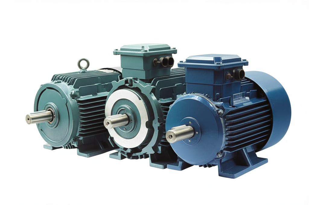
Types of Three-Phase Motors and Where They Fit
Three-phase motor is a broad category. You have several subtypes tailored for different needs.
- Three-phase induction motors (asynchronous): The most common motor in industry by far. Rugged. Cost-effective. Self-starting. Available in squirrel cage and wound rotor forms.
- Squirrel cage induction motor: A cast or fabricated rotor with bars and end rings. Simple and reliable. Great for pumps, fans, compressors, and conveyors.
- Wound rotor induction motor: Rotor windings connect to external resistors through slip rings. Offers high starting torque and adjustable speed in legacy systems though VFDs largely replaced this approach.
- Three-phase synchronous motors: The rotor locks to the stator’s rotating field using field windings or permanent magnets.
- Field-excited synchronous motor: Precise speed at the grid frequency. Can correct power factor when overexcited. Common in large industrial drives and compressors.
- Permanent magnet synchronous motor (PMSM): High torque density and high efficiency. Popular for servo drives, robotics, and electric vehicles. Often controlled with advanced VFDs using FOC or vector control.
- Brushless DC (BLDC) motors: Electrically similar to PMSMs but controlled as trapezoidal back EMF machines. Great for fans, pumps, and appliances that need compact size with efficient speed control.
- Switched reluctance motor (SRM): A different animal with salient poles and no rotor windings. Tough and simple rotor. Good in harsh environments though acoustic noise and torque ripple must be managed by control.
No matter which you choose the lamination stacks in the stator and rotor still set a baseline for loss, torque ripple, and noise. PMSMs push flux density higher which brings greater sensitivity to lamination thickness and material quality. Induction motors see wide voltage and frequency swings on VFDs which raise the stakes for coatings and stress relief.
Three-Phase vs Single-Phase: A Quick Comparison
If you are weighing three-phase against single-phase for an application here is the quick take.
- Power supply: Three-phase power is standard in industrial facilities. Residential sites are usually single-phase.
- Starting: Three-phase motors are self-starting. Many single-phase motors need auxiliary windings, capacitors, or start mechanisms that add cost and failure points.
- Efficiency and power density: Three-phase wins at higher power. You get more horsepower per frame and better efficiency.
- Cost and complexity: The motor itself is usually simpler and more robust in three-phase when power is available. The wiring and protection gear may cost more in small facilities without three-phase service.
- Torque ripple and vibration: Three-phase produces smoother torque which reduces vibration and noise.
If you can get three-phase power you will usually choose a three-phase motor for anything beyond small fractional horsepower loads.
Material Choices for Laminations: Silicon Steel, Cobalt, and More
Now we get to the heart of motor laminations and how they relate to efficiency, temperature rise, and cost. Your core material and thickness set the tone for loss and performance.
- Non-oriented silicon steels (CRNGO): The bread and butter choice for three-phase motors. The grain structure is not oriented which gives reasonably uniform magnetic properties in all directions. Available in grades that trade off cost and losses with thicknesses like 0.50, 0.35, 0.30, 0.27, and 0.20 mm. Thinner gauges reduce eddy current loss but increase cost and can be harder to punch.
- Pros: Balanced performance and cost. Good for most induction motors and many PMSMs.
- Cons: Not as low loss as premium cobalt or amorphous materials. Thinner gauges require excellent tooling and process control.
- Oriented silicon steels (CRGO): Designed with grains aligned for a preferred direction which makes them ideal for transformers with consistent flux direction.
- Pros: Very low loss along the rolling direction. Excellent for transformer cores.
- Cons: Not ideal for rotating machines that see changing flux directions.
- Cobalt-iron alloys: Used when you need very high flux density and high power density or when you run at elevated temperatures.
- Pros: Higher saturation flux density and low loss in some operating regions. Great for aerospace or high-speed machines.
- Cons: Very expensive. Harder to process. Only justified when performance requires it.
- Amorphous and nanocrystalline alloys: Exceptional low loss at high frequency and low flux density which makes them attractive for high-efficiency transformers. Limited use in motors due to brittleness and processing challenges though interest grows for specialty high-frequency machines.
- Coatings and insulation classes: Electrical steel arrives with coatings like C3 or C5 types that set interlaminar resistance and affect welding and bonding. Choose coatings compatible with your joining method and temperature profile. For insulation of windings choose classes like F or H based on expected temperature rise and environment.
For a broad overview of material options and use cases you can review common electrical steel laminations. The key is to map your duty cycle and frequency content to the material loss curves. Then weigh cost and manufacturability against the efficiency gain you need to hit IE3 or IE4.
Manufacturing and Assembly: Stamping, Laser, Bonding, and Quality Factors
Material selection is only half the story. How you cut, stack, and secure laminations can raise or sink your efficiency and acoustic performance.
- Stamping and progressive dies: The go-to process for high-volume motor laminations. Stamping offers the lowest cost per part at scale and delivers tight repeatability. Tooling cost is significant but it pays off for production. Control burr height because burrs can bridge insulation and increase eddy currents. Monitor die wear closely.
- Laser cutting: Ideal for prototypes, pilot builds, and complex geometries. Laser cutting has a heat-affected zone that increases local losses if you skip stress relief. Plan for an anneal cycle when needed and tune parameters to minimize HAZ. Laser is slower than stamping but avoids high upfront tooling.
- Wire EDM: Excellent edge quality with minimal heat input. Too slow and expensive for high volume but great for precision laminations and test articles.
- Waterjet: No heat input but slower and less common for electrical steel. Taper and edge finish must be managed.
- Interlocking, welding, riveting, and bonding:
- Mechanical interlocks: Think of these like LEGO bricks that snap laminations together to form a rigid core. No heat input. Good for production. Slightly reduces stacking factor and needs precise tooling.
- Riveting and cleating: Simple and robust but can introduce local stress and minor loss impacts.
- Welding: Strong joints but heat can raise local core losses unless you limit welds and use appropriate coatings or post-weld anneal.
- Adhesive bonding and bake bonding: Excellent for damping vibration and lowering noise. Often improves core integrity and can raise stacking factor. Requires controlled cure processes.
- Stacking factor and dimensional control: Stacking factor is the ratio of steel thickness to total stack thickness. Higher stacking factor means more magnetic material and more torque per stack length. Good process control minimizes trapped air and coating buildup that reduce stacking factor.
- Skew and slot geometry: Skewing rotor bars by a fraction of a slot pitch reduces cogging torque and acoustic noise. Slot shapes and tooth tip designs influence harmonics and losses.
- Rotor bar material: Aluminum die casting is common and cost effective. Copper rotor bars lower rotor I2R losses and boost efficiency at the cost of more complex casting or fabrication.
- Stress relief and annealing: Cutting introduces residual stress that harms magnetic properties. Proper annealing restores performance especially for laser cut or punched parts in thin gauges.
Solid lamination manufacturing drives real performance. When you source cores ask for measured core loss at your target flux density and frequency across several points. Verify burr height, coating integrity, skew angle, slot tolerances, and stack squareness. You can find a helpful overview of end-to-end options under motor core laminations.
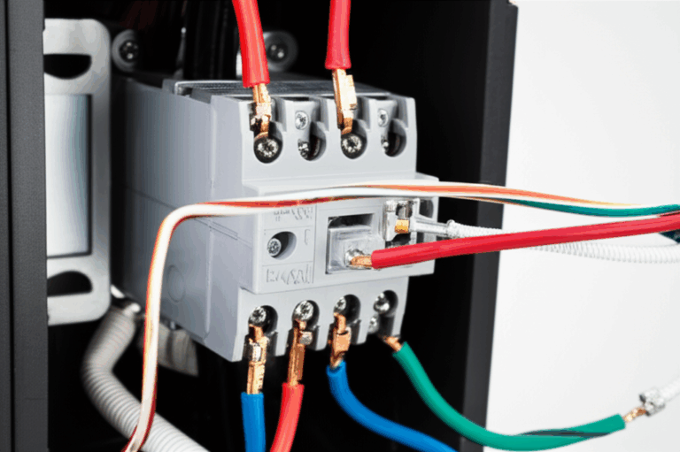
Power Electronics and Control: Star/Delta, VFDs, Starters, Protection
Three-phase motors live inside larger electrical systems. The way you connect and control them sets startup behavior, efficiency, and reliability.
- Delta and wye (star) connections: Windings can be connected in delta or wye to suit line voltage and starting current requirements. Many motors support dual voltage by reconfiguring the terminal connections. Delta uses higher line current for the same power. Wye has lower line current which can help during start.
- Starters:
- DOL (Direct on Line): Simple and robust for small to mid-size motors with acceptable inrush current and mechanical shock.
- Star-delta: Reduces inrush current by starting in wye then switching to delta. Useful where line current limits matter.
- Soft starters: Ramp voltage and limit inrush. Reduce mechanical shock and extend machine life at a lower cost than VFDs when you only need smooth starts.
- Variable Frequency Drives (VFDs): The most impactful control for energy savings and process control. You set motor speed by changing frequency and voltage. For pumps and fans this often cuts energy use by 20 to 50 percent because power scales roughly with the cube of speed in variable torque loads. Use VFDs with motors rated for inverter duty. Consider bearing protection for common-mode voltages. Employ filters if cable runs are long or if you face EMC constraints.
- Protection and safety: Overload protection prevents thermal damage from sustained overcurrent. Short circuit and ground fault protection saves equipment from faults. Phase-loss and unbalance relays catch single phasing before damage spreads. MCCs and smart relays add monitoring which supports predictive maintenance.
- Regenerative braking: With the right VFD and DC bus configuration you can capture energy when the load drives the motor. Elevators, conveyors on declines, and high-inertia loads benefit from regen.
- Power factor correction: Induction motors draw magnetizing current that lowers power factor at light loads. Banks of capacitors or synchronous motors can correct power factor at the system level.
Control strategy and protection settings must match the motor construction, insulation class, and environment. VFD duty applications especially need attention to heat, harmonics, and insulation stress.
Matching Solutions to Applications
Different applications reward different motor and lamination choices. Here is a quick mapping to get you started.
- Pumps and fans (HVAC, water treatment, process): Three-phase induction motors with VFDs excel here. Use thin-gauge silicon steel for lower core loss and low-noise stacks. Pay attention to VFD harmonics and specify inverter-duty windings and bearings. Expect large energy savings by matching speed to demand.
- Compressors and blowers: Induction or synchronous motors depending on size and process control. For high-power density and tight speed regulation consider PMSMs. Use robust stator stacks with skew to limit tonal noise.
- Conveyors and material handling: Induction motors with vector drives provide smooth speed control and torque at low speed. Wound rotor legacy systems still exist but VFDs usually win on efficiency and maintenance.
- Machine tools and robotics: PMSMs and servos lead due to torque density and precision. Laminations in these motors often use thinner gauges and high-grade steels to keep core loss low at higher speeds.
- Elevators and hoists: Regenerative drives with induction or PMSM. Design for high torque at low speed and plan for regen energy handling.
- Electric vehicles and traction: PMSMs dominate for efficiency and torque density though SRMs and induction motors remain in play. Lamination choices here are critical to handle high frequency content and temperature.
- Renewable generation: Wind turbines often use three-phase generators that are synchronous or doubly-fed induction machines. Laminations matter for efficiency and thermal management in nacelles with tight cooling.
Whatever the application the stator and rotor stacks remain central to efficiency and reliability. For a deeper look at stator stack options you can review stator core lamination and pair it with the matching rotor core lamination.
Specs That Matter: Ratings, Efficiency Classes, and Standards
When you build a spec or read a nameplate here is what you should care about and why it matters.
- Voltage and frequency: Match your grid or drive output. Many motors are rated 230/400 V or 460/690 V at 50/60 Hz. Dual-frequency design affects flux density and loss so coordinate with your lamination supplier if you need global compatibility.
- Power and torque: Horsepower or kilowatt ratings define output. Torque ties directly to flux and current. High starting torque applications may push you toward wound rotor or vector-controlled drives.
- Speed and poles: Synchronous speed depends on line frequency and pole count. Slip sets actual induction motor speed under load. If you need precise speed choose synchronous or use a VFD with feedback.
- Efficiency class: IE2, IE3, IE4, and NEMA Premium define minimum efficiencies. Hitting IE3 or IE4 often requires better lamination steel, thinner gauges, and tighter manufacturing control. Test methods follow standards like IEC 60034 and IEEE 112.
- Service factor: A motor with a service factor of 1.15 can handle 15 percent overload under defined conditions. Good for intermittent overloads and thermal headroom.
- Insulation class and temperature rise: Class F and H dominate modern designs. Pair a lower temperature rise with a higher class to extend life. VFD duty may require upgraded insulation to handle dv/dt.
- Enclosure and cooling: TEFC, TENV, ODP, and specialty cooling like TEAO or water jacketed options control how the motor manages heat. Cooling method affects noise and maintenance.
- Bearings and lubrication: Choose sealed or regreasable based on duty and environment. Consider insulated bearings or shaft grounding for VFDs.
- Noise and vibration: Specify limits per ISO or NEMA standards if your application has acoustic requirements. Control slot combinations and skew to reduce tonal noise from electromagnetic forces.
- Compliance and standards: IEC and NEMA frame sizes, shaft heights, and mounting dimensions drive interchangeability. Follow UL or CE for safety. Use MCCs that meet your region’s electrical codes.
A clean spec saves time and rework. It also helps your lamination partner propose the right steel grade and thickness with realistic cost and lead time.
Practical Procurement Checklist and Next Steps
You have the fundamentals. Now turn them into action. Use this checklist to drive a productive conversation with your team and suppliers.
- Define the duty profile:
- Load type: variable torque, constant torque, or constant power
- Expected speed range and control method: fixed speed, soft start, or VFD
- Duty cycle and annual run hours
- Environment: ambient temperature, altitude, humidity, dust, chemicals
- Set performance targets:
- Efficiency class: IE3 or IE4 for most industrial upgrades
- Power factor and starting torque requirements
- Noise and vibration limits
- Choose core materials and lamination thickness:
- Start with non-oriented silicon steel and pick thickness to meet loss targets at your frequency range
- Consider cobalt or specialized alloys only if power density demands it
- Confirm coating class, interlaminar resistance, and weld or bond compatibility
- Request core loss data at relevant flux densities and frequencies
- Select manufacturing methods:
- Stamping for volume and cost
- Laser or EDM for prototyping or complex small batches with planned stress relief
- Pick joining method based on acoustic and structural needs: interlock, weld, rivet, or bond
- Validate the stack and assembly:
- Measure stacking factor, burr height, slot geometry, and skew
- Verify stress relief and annealing where needed
- Check rotor balance and shaft fits
- Confirm nameplate ratings and derating when running on VFDs at nonstandard frequencies
- Plan power electronics and protection:
- Pick DOL, star-delta, soft starter, or VFD based on process needs
- Add filters and bearing protection if you run long cables or high switching frequencies
- Specify overload, short circuit, and ground fault protection with phase-loss detection
- Budget and timeline:
- Weigh tooling cost for stamping against unit cost and lead time
- Align material availability with your production ramp
- Documentation and testing:
- Ask for lamination material certifications and coating specs
- Require core loss and stack dimensional reports
- Run witnessed tests where the application is mission critical
If you are new to lamination sourcing or you want a quick sanity check start with an experienced lamination partner. They can show you trade-offs among gauges, coatings, and joining methods for your exact frequency and flux density. You can also browse common options for motor core laminations to see typical constructions and applications.
Your Engineering Takeaway
- Three-phase motors dominate industry because they deliver smooth torque, high efficiency, and robust starting with minimal fuss.
- The stator and rotor lamination stacks set your efficiency ceiling. Material grade, thickness, coating, and manufacturing quality drive core loss more than any single design choice.
- You reduce core loss by breaking up eddy currents with thin, insulated laminations and by choosing steels with low hysteresis loss at your operating flux density.
- VFDs unlock 20 to 50 percent energy savings in variable torque applications and they reshape your design constraints. Plan for harmonics, insulation stress, and bearing protection.
- Material selection and manufacturing process must match your volume and performance goals. Stamping wins for volume. Laser and EDM support fast development and complex parts with stress relief.
- For IE3 and IE4 targets expect to use thinner gauges, higher grade silicon steel, precise stacking, and low-loss joining methods like bonding or optimized interlocks.
- A clear spec and a data driven RFQ save time. Ask for core loss curves, stacking factor, and dimensional control. Validate with tests that match your duty cycle.
Next steps. Align your application requirements with a lamination strategy you can produce repeatably. If you want to discuss stator stacks, rotor options, and coating classes for your design schedule a technical review with your lamination supplier. Bring your target flux density, frequency range, and efficiency class. You will leave that call with a shortlist of materials, thicknesses, and manufacturing options that hit your performance and cost goals.
—
By approaching three-phase motors through the lens of laminations you focus on the part of the design that most affects efficiency and heat. That is where the watts go to die. Control the material and the process then pair the motor with the right drive and protection. Do that well and your system runs cooler, lasts longer, and costs less to operate. That is the kind of engineering win your team and your CFO will feel all year.