What Are Stator Windings? The Core Component of Electric Motors & Generators Explained
As an engineer or designer, you’re constantly making decisions that balance performance, cost, and reliability. Every component choice matters, but few are as fundamental to an electric machine’s function as the stator windings. If you’ve ever needed to specify a motor, troubleshoot a generator, or simply understand the “why” behind your design’s efficiency, you’ve come to the right place. Understanding stator windings isn’t just academic; it’s the key to unlocking better performance and making more informed engineering decisions.
These coiled wires, tucked away inside the stationary frame of a motor or generator, are the unsung heroes of energy conversion. They are the conduits through which electrical energy is transformed into the magnetic force that creates motion or, conversely, the pathways where mechanical motion induces the flow of electricity. Getting them right is critical.
This guide will demystify stator windings, moving from foundational principles to practical applications. We’ll break down the engineering concepts in clear, accessible terms to empower you in your next design review or procurement discussion.
In This Article
- Defining Stator Windings: The Conductive Coils
- How Stator Windings Work: Principles of Energy Conversion
- Types and Configurations of Stator Windings
- Common Failure Modes: Why Windings Go Wrong
- The Critical Importance and Applications of Stator Windings
- Your Engineering Takeaway: Key Principles for Design and Specification
Defining Stator Windings: The Conductive Coils
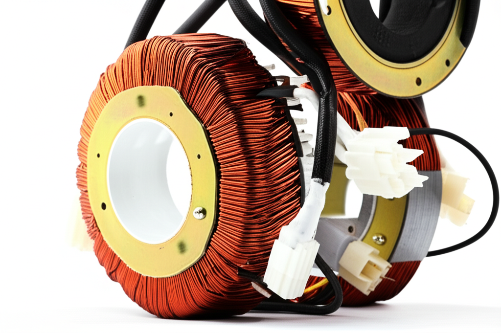
Let’s start with the fundamentals. At its core, a stator winding is a meticulously arranged set of conductive wires, typically made of insulated copper or aluminum, that are placed into the slots of a stator—the stationary part of an electrical machine.
Think of the relationship between the two main parts of a motor: the stator and rotor. The stator is the fixed, outer housing, and the rotor is the rotating component inside. The stator windings are the “engine” housed within that fixed frame. Their primary purpose is either to generate a powerful magnetic field (in a motor) or to have a magnetic field pass through them to generate electricity (in a generator). It’s this interaction across the air gap between the stator and rotor that makes the magic happen.
To truly grasp what they are, let’s break down their key components:
- Conductor Material: This is the wire itself. Copper is the industry standard due to its excellent electrical conductivity, which translates to higher efficiency. For the same current, a copper wire can be smaller than an aluminum one, allowing for more compact and power-dense designs. However, aluminum is sometimes used in specific applications where its lighter weight and lower cost outweigh the performance trade-offs.
- Insulation System: This is arguably the most critical and failure-prone part of the winding. Each strand of magnet wire is coated with a thin layer of enamel insulation to prevent the turns of the coil from shorting against each other. Additionally, slot liners made of materials like Nomex or Mylar protect the windings from the sharp edges of the stator core. Finally, the entire assembly is often impregnated with varnish, which helps with heat dissipation, provides mechanical rigidity, and protects against moisture and contaminants.
- Stator Core: The windings don’t just float in space; they are housed within the stator core. This core is built from stacks of thin silicon steel laminations. The laminated construction is crucial for minimizing energy losses, a topic we’ll explore in detail next. The core has slots punched into it where the windings are carefully placed.
How Stator Windings Work: Principles of Energy Conversion
Understanding how stator windings function comes down to a few core principles of physics, primarily electromagnetism and Faraday’s Law of Induction. You don’t need a Ph.D. in physics, but grasping these concepts will give you a powerful intuitive understanding of your designs.
Generating a Magnetic Field (The Motor Principle)
The fundamental principle of an electric motor is that an electric current flowing through a wire creates a magnetic field around it. When you coil that wire, you concentrate this magnetic field, creating an electromagnet. This is exactly what a stator winding is: a collection of precisely shaped electromagnets.
In an AC motor, something truly elegant happens. By feeding alternating current to different sets of windings (or “phases”) arranged around the stator, you create a Rotating Magnetic Field (RMF). You can visualize this RMF as a “magnetic wave” that rotates around the inside of the stator at a specific speed (the synchronous speed). This rotating field then “drags” the rotor along with it through magnetic attraction and repulsion, producing the mechanical force we call torque. It’s a non-contact transfer of energy, all orchestrated by the stator windings.
Inducing Voltage (The Generator Principle)
Now, let’s flip the script. What if instead of feeding electricity into the windings, you use an external force (like a wind turbine or a diesel engine) to spin a magnetic rotor inside the stator?
This is where Faraday’s Law of Induction comes into play. Faraday discovered that if you move a conductor through a magnetic field (or move a magnetic field past a conductor), you induce a voltage—and therefore a current—in that conductor. In a generator or alternator, the rotating magnetic field from the rotor sweeps across the stationary stator windings. This change in magnetic flux induces an Electromotive Force (EMF), which is just another name for voltage. This induced voltage drives the flow of electric current out of the generator and into the power grid or your car’s battery.
In both cases, motor and generator, the stator windings are the indispensable interface for energy conversion. They are either turning electricity into a dynamic magnetic field or turning a dynamic magnetic field into electricity.
Types and Configurations of Stator Windings
Not all stator windings are created equal. Their design and configuration are tailored to the specific application, voltage, and performance requirements of the machine. As a designer or procurement manager, knowing these differences helps you specify the right motor or generator for the job.
Classification by Electrical Phase
- Single-Phase Windings: These are common in smaller, lower-power applications that run on standard household electricity. Think of the motors in your refrigerator, fans, or power tools. They are simpler and less expensive but generally less efficient and require extra components (like a start winding or capacitor) to initiate rotation.
- Three-Phase Windings: The workhorse of the industrial world. These windings consist of three separate sets of coils, spaced 120 electrical degrees apart. When energized by a three-phase AC supply, they naturally produce a smooth, rotating magnetic field without needing any extra starting components. This makes them more efficient, powerful, and reliable. You’ll find them in everything from large industrial pumps and conveyors to the traction motors in electric vehicles.
Classification by Winding Method
The physical pattern in which the coils are inserted into the stator slots also has a significant impact on performance.
- Random-Wound Windings: This is the most common method for smaller motors. As the name suggests, insulated wires are wound into the stator slots in a less structured, “random” pattern. It’s a highly automated and cost-effective process, but it results in air gaps between the wires, which slightly reduces the slot fill factor and can create hot spots.
- Form-Wound Windings (or Hairpin Windings): Used in larger, high-voltage, or high-performance machines, these windings are made from pre-formed rectangular conductors. These “hairpins” or coils are individually shaped, insulated, and then precisely inserted into the slots. This method achieves a much higher slot fill factor—sometimes over 70% compared to 40-50% for random-wound. According to automotive engineering research, this is a key technology in modern EV motors, where it contributes to 3-5% efficiency gains and a significant increase in power density. The result is a more efficient motor that can handle higher currents and dissipate heat more effectively.
Materials and Insulation Systems
Beyond the pattern, the materials themselves are a critical design choice.
- Conductor: Copper vs. Aluminum: As mentioned, copper is the leader in performance. Its superior conductivity means lower I²R losses (heat generated by electrical resistance). In comparable motor designs, choosing copper over aluminum can result in a 1-3% increase in overall efficiency. While aluminum is lighter and cheaper, it requires a larger cross-sectional area to carry the same current, which can lead to a larger, less power-dense motor.
- Insulation Class: The insulation system is the guardian of the motor’s lifespan. Its ability to withstand heat is defined by its insulation class (e.g., Class F, Class H). A fundamental rule of thumb, backed by NEMA and IEC standards, is that for every 10°C you operate a motor above its insulation’s temperature rating, you cut its expected life in half. A Class F system is rated for 155°C, while a Class H system can handle 180°C. Specifying a higher insulation class can be a cost-effective way to build in a significant reliability margin, especially for critical applications.
Common Failure Modes: Why Windings Go Wrong
For engineers and maintenance managers, understanding why windings fail is just as important as knowing how they work. Studies by organizations like IEEE and the Electric Power Research Institute (EPRI) consistently show that stator winding insulation failure is the culprit in 30-50% of all motor failures, making it the single most common root cause.
Here are the primary ways windings can fail:
- Turn-to-Turn Short: The insulation between two wires in the same coil fails. This creates a small, localized closed loop that acts like the secondary of a transformer, generating intense heat and leading to rapid failure.
- Phase-to-Phase Short: Insulation fails between two different phase windings, causing a massive and destructive flow of current.
- Ground Fault: The insulation between a winding and the steel stator core fails, allowing current to leak to the motor frame. This is a serious safety hazard and will typically trip protective devices immediately.
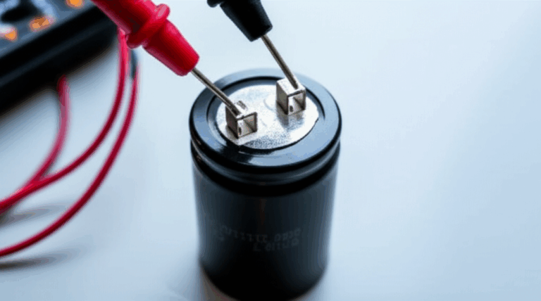
Regular diagnostic testing, such as using a megohmmeter (or “megger”) to measure insulation resistance, is a cornerstone of any predictive maintenance program to catch these issues before they lead to catastrophic failure.
The Critical Importance and Applications of Stator Windings
From the tiniest motor in a medical device to the massive generators in a hydroelectric dam, stator windings are the linchpin of our electrified world. Their design and quality directly influence a machine’s most important characteristics:
- Efficiency: The resistance of the windings is a primary source of energy loss in a motor (known as copper loss or I²R loss). These losses can account for 20-40% of the total energy waste in a standard induction motor. Better winding design and materials directly translate to lower energy consumption and reduced operating costs.
- Power Density: The amount of power a motor can produce for its size is heavily dependent on how effectively the windings can carry current and dissipate heat. Advanced techniques, like the use of form-wound coils in high-quality core lamination stacks, maximize the amount of copper in the stator, boosting power output without increasing the motor’s physical footprint.
- Reliability: As we’ve seen, the insulation system is often the weakest link. A well-designed, robustly insulated winding is the foundation of a long and reliable service life.
Their applications are virtually limitless:
- Industrial Machinery: Powering pumps, fans, compressors, and manufacturing lines in every industry.
- Home Appliances: From the compressor in your air conditioner to the drum motor in your washing machine.
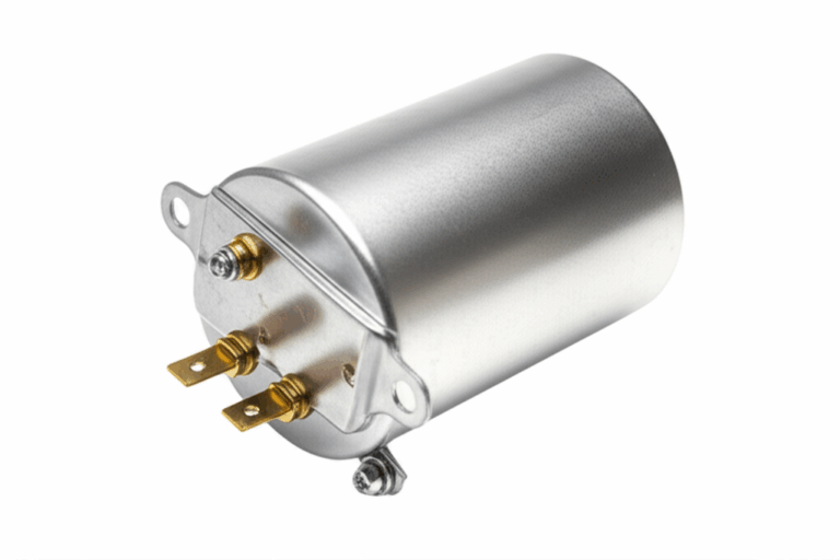
- Automotive: Driving electric vehicles and operating as alternators to charge batteries in internal combustion engine cars.
- Power Generation: At the heart of every power plant, from massive wind turbines and hydroelectric generators to nuclear and fossil fuel facilities.
- Aerospace & Defense: Used in high-performance actuators, guidance systems, and other critical equipment where reliability is non-negotiable.
Your Engineering Takeaway: Key Principles for Design and Specification
Understanding stator windings empowers you to ask the right questions and make smarter choices. Whether you are designing a new product or procuring motors for a facility, keep these key takeaways in mind:
- Function Dictates Form: The choice between single-phase and three-phase, or random-wound versus form-wound, depends entirely on your application’s requirements for cost, efficiency, and power.
- Insulation is an Investment: Don’t skimp on the insulation class. Specifying a higher class than strictly necessary is often a low-cost insurance policy against premature failure, especially in demanding environments.
- Efficiency Has a Payback: While a motor with higher-quality copper windings might have a slightly higher upfront cost, the energy savings over its lifetime can provide a significant return on investment.
- The System Matters: The windings don’t work in a vacuum. Their performance is inextricably linked to the quality of the motor core laminations they are housed in and the drive system that powers them.
Stator windings are more than just coils of wire; they are the active, energy-converting heart of nearly every electric motor and generator. By grasping these fundamental principles, you are better equipped to design, specify, and operate electrical machines that are more efficient, more powerful, and more reliable.