What Does a Servo Motor Do? Unlocking Precision in Motion Control
Every engineer who works with motion control hits the same moment. You need a motor that moves to the right place, at the right speed, with the right torque, then holds position without wandering. You also need it to do that all day, under load, with minimal heat and minimal noise. That’s the heart of the question behind “what does a servo motor do?” It doesn’t just spin. It controls motion precisely. It checks itself. It corrects in real time. And here’s the part that often gets overlooked. The quality of the motor’s lamination stack quietly makes or breaks that promise of precision.
If you’re weighing AC vs DC servo options, encoder vs resolver feedback, or laser-cut vs stamped laminations for production, you’re in the right place. I’ll walk you through the engineering fundamentals first, then guide you on materials and manufacturing choices that directly affect performance, efficiency, cost, and reliability. You’ll leave with a practical checklist and a clear next step.
In This Article
- Introduction: The Engine of Accuracy in Modern Technology
- What Exactly Is a Servo Motor? A Clear Definition
- How a Servo Motor Works: The Closed-Loop System Explained
- Engineering Fundamentals: Core Losses and Why Laminations Matter
- Key Characteristics and Advantages of Servo Motors
- Where Servo Motors Are Used: Common Applications
- Material Choices for Motor Core Laminations
- Manufacturing and Assembly Processes: What Changes Performance and Cost
- Servo Motors vs Stepper Motors: A Practical Comparison
- Choosing the Best Fit for Your Application
- Practical Design and Procurement Checklist
- The Business Case: Efficiency, Throughput, and Lifecycle Cost
- Your Engineering Takeaway
Introduction: The Engine of Accuracy in Modern Technology
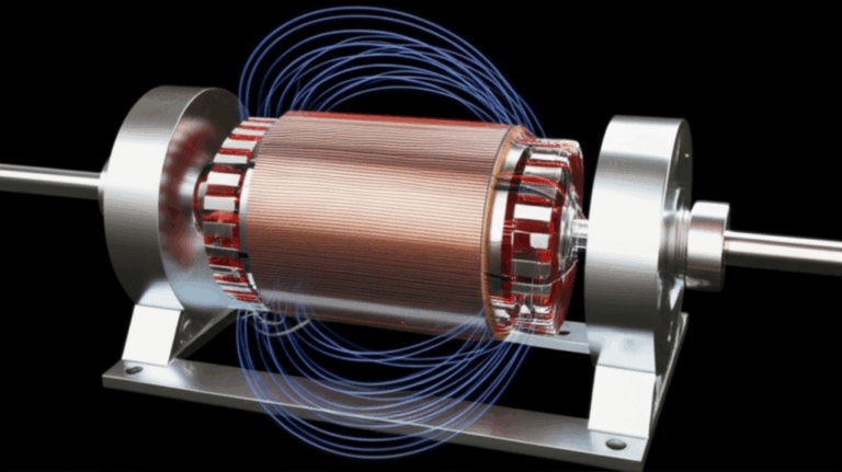
Servo motors power the precision behind modern automation. You’ll find them in industrial robots, CNC machining centers, packaging machinery, medical devices, camera gimbals, drones, and aerospace actuators. They respond quickly. They hold position with authority. They deliver high torque at low speeds. They do all this by combining a motor, a drive, a controller, and a feedback device into a closed-loop control system.
Now let’s pull the curtain back on what really drives that performance. The lamination stack inside the stator and rotor governs magnetic behavior, loss, heating, torque ripple, and acoustic noise. In short, it governs how “servo-like” your servo feels. If you care about positional accuracy, quick response, smooth operation, and energy efficiency, you should care about core laminations.
What Exactly Is a Servo Motor? A Clear Definition
A servo motor is an electromechanical actuator that precisely controls angular or linear position, velocity, and torque. It sits in a closed-loop system. The controller sends a command. The feedback device (encoder, resolver, or potentiometer in RC servos) reports the actual state. The drive adjusts power to minimize error. That loop runs constantly. You get real-time control, error correction, and the ability to tune dynamic response with a PID controller.
Two quick distinctions:
- Servo vs standard motor: A standard motor spins when you apply voltage. A servo motor participates in a closed-loop system with encoder feedback or resolver feedback. It corrects to achieve the commanded state.
- Servo vs servo system: A servo system includes the motor, drive/amplifier, controller, feedback sensor, and often a gearbox or transmission. The magic happens in the system, not just in the motor alone.
Servo motors can be AC or DC. Brushed or brushless. Rotary or linear. Most industrial servos today are brushless AC designs (often permanent magnet synchronous machines or BLDC types) with high-resolution encoders. RC servos for hobby and small mechatronics use brushed or brushless DC motors with a simple onboard controller and a potentiometer or basic encoder.
How a Servo Motor Works: The Closed-Loop System Explained
Core Components
- Motor: Usually an AC brushless (BLDC/PMSM) or DC motor that produces motion. A precision motor with a high-performance magnetic circuit forms the backbone of servo behavior.
- Sensor/Encoder: Reports position and speed. Common options include rotary encoders, linear encoders, resolvers, potentiometers in RC servos, and Hall effect sensors for commutation.
- Controller: Compares the command to the feedback. It computes error and applies a control law (often a PID controller) to reduce error to zero or near zero.
- Drive/Amplifier: Converts command signals into motor currents. It uses pulse width modulation (PWM), commutation logic, and current regulation to deliver torque and speed. For DC servos you’ll often see an H-bridge.
The Feedback Loop in Action
- You command position or velocity from a PLC, a motion controller, or an embedded microcontroller.
- The motor starts to move.
- The encoder sends real-time data on position and speed to the controller.
- The controller computes error. It adjusts the drive output to reduce that error.
- The motor corrects until the command and feedback align. Just like you steer a car and make constant micro-corrections to stay centered in your lane.
That closed loop is why servos deliver positional accuracy and quick response under changing loads. The loop fights disturbances. The motor laminations inside the stator and rotor quietly set the stage by reducing magnetic losses and shaping the magnetic flux. Better laminations improve thermal behavior, smoothness, and efficiency. That makes the controller’s job easier.
Engineering Fundamentals: Core Losses and Why Laminations Matter
Here’s the physics in plain English. When the motor’s magnetic field changes, two types of losses show up in the core: hysteresis loss and eddy current loss.
- Hysteresis loss: Think of it as the energy you spend flipping the direction of magnetic domains as the field swings along the B-H curve. Materials with lower coercivity (resistance to being demagnetized) reduce this loss. Good electrical steels are engineered for this purpose.
- Eddy current loss: Imagine small whirlpools in a river. A changing magnetic field induces circulating currents inside a solid steel core. Those “whirlpools” waste energy as heat. Laminations stop large whirlpools from forming. Thin, insulated sheets break the path for those currents. The thinner the lamination, the smaller the eddy currents, and the lower the loss at higher frequencies.
Why this matters in servo motors:
- Servo drives switch currents fast. They modulate with PWM at high frequencies. The machine itself may run at high electrical frequency because of pole count and speed. Both effects raise eddy current losses.
- Less core loss means lower operating temperature and higher efficiency. It also means better dynamic performance since magnetic properties stay consistent as you heat up.
- High-quality laminations improve smoothness. They help reduce torque ripple and acoustic noise by enabling precise flux paths. Lamination geometry and slot design also matter.
A few practical notes:
- Lamination thickness: Common thicknesses for nonoriented electrical steel in motors include around 0.35 mm down to 0.20 mm for high-frequency or high-performance designs. Thinner laminations reduce eddy currents at the cost of more sheets, higher manufacturing complexity, and potentially longer stacking times.
- Insulation coatings: Each lamination receives a thin insulating coating to block eddy currents between sheets. Coating choice affects punchability, interlaminar resistance, and bonding compatibility.
- Frequency sensitivity: As electrical frequency rises, eddy current loss rises roughly with the square of frequency. Thin laminations become more valuable in high-speed spindles, compact motors with high pole counts, and fast-switching drives.
If you’re visual, picture the magnetic field as water flowing through a sponge. Magnetic permeability is how easily the sponge soaks up water. Good electrical steel is a sponge for magnetic flux. Laminations slice the sponge into sheets that block sideways flow. That’s how you tame those whirlpools.
Key Characteristics and Advantages of Servo Motors
- High positional accuracy and repeatability: Hold a commanded position with minimal drift. Use high-resolution encoders to drive error toward zero.
- Precise speed control: Maintain speed despite load changes. The closed loop fights disturbances.
- High torque at low speeds: Deliver torque even near stall. That’s where steppers can struggle under load.
- Quick response and acceleration: Hit full torque in milliseconds. Small settling times improve throughput.
- Excellent dynamic performance: Handle rapid profile changes with well-tuned PID or model-based control.
- Smooth operation: Lower torque ripple and reduced vibration. The right lamination stack and slot design help.
- Energy efficiency: Draw power proportional to load. Add regenerative braking where possible.
- Robustness: With the right design, you get high reliability in harsh environments.
Where Servo Motors Are Used: Common Applications
You’ll see servo motors anywhere precise motion matters.
- Industrial automation and robotics: Six-axis robot arms, SCARAs, collaborative robots. Servos sit on most robot joints. Repeatability often reaches the sub-millimeter range.
- CNC machining: Mills, lathes, routers. Servo-driven axes and spindles deliver tight tolerances and controlled acceleration. High-resolution encoder feedback feeds the CNC controller.
- Packaging machinery: Filling, sealing, labeling, cutting. Precise timing and position control boost line throughput and reduce scrap.
- Medical and pharmaceutical: Surgical robots, diagnostic imaging axes, lab automation, catheter manufacturing. Precision and smoothness support quality and safety.
- Aerospace and defense: Flight control surfaces, antenna pointing systems, seekers. Reliability and power density dominate the trade space.
- Consumer and hobby: Camera gimbals, drones, model aircraft, RC servos. Micro servos and standard servos leverage PWM control and onboard electronics.
- Printing and textile: Controlled tension, accurate feeding, and synchronized cutting.
- AGVs and AMRs: Motorized wheels and actuators for autonomous material handling.
- Precision agriculture, semiconductor production, food and beverage processing, and more: Motion control threads through modern manufacturing.
Industry studies point to strong growth in servo motors and drives, with Asia-Pacific playing a major role due to manufacturing expansion. Robotics use continues to rise. Servo motors enable large efficiency gains and significant throughput improvements when you tune both mechanics and controls well.
Material Choices for Motor Core Laminations
This is where you make or lose a lot of performance. Materials define magnetic behavior, core loss, and thermal stability. They also affect cost and manufacturability.
- Nonoriented electrical steels (NOES, often called silicon steels or M-grades): The workhorse for rotating machines. These steels balance low loss, decent saturation, and cost. They perform across multiple directions of flux travel which suits motors. You’ll choose grade and thickness based on your electrical frequency and efficiency targets. See more about available grades and coatings in the overview of electrical steel laminations.
- Grain-oriented electrical steel (GOES): Fantastic in transformers along a preferred direction of flux. Less common in motors which see rotating flux. Use NOES for servo motors unless you have a rare, oriented flux design.
- Cobalt-iron alloys (Fe-Co): High saturation flux density and excellent performance at higher frequencies. Great for high power density aerospace or high-speed spindles. The trade-off is cost and more demanding manufacturing.
- Specialized low-loss silicon steels: Thinner gauges with engineered coatings can deliver lower eddy current loss and better efficiency at higher electrical frequencies. Cost rises as thickness falls. Often worth it in compact servo packages.
- Powdered iron or soft magnetic composites: Useful in some special high-frequency or 3D flux paths. Not common in standard servo stators and rotors but valuable in niche designs.
Pro tip: Match lamination thickness to your electrical frequency and switching strategy. If your servo runs a high pole count at high speed with a high PWM frequency, you’ll benefit from thinner laminations. That choice pays off in lower core loss and cooler operation.
For deeper context on how the lamination stack underpins servo performance across stator and rotor, review this overview on motor core laminations.
Manufacturing and Assembly Processes: What Changes Performance and Cost
Material selection sets the ceiling. Manufacturing determines how close you get to it. Processes affect magnetic properties, tolerances, noise, and long-term stability.
- Stamping: The standard for volume production. Progressive die stamping offers excellent repeatability and cost efficiency once tooling is in place. Watch for burrs, edge deformation, and residual stress. These can increase core loss and noise. Tooling cost is the main upfront investment.
- Laser cutting: Excellent for prototypes, complex geometries, and low-volume runs. Minimal tooling cost and quick iteration. Heat-affected zones can increase local loss. Good process parameters and post-processing mitigate this.
- Wire EDM: Very precise with virtually no burrs or HAZ. Slower and more expensive. Great for high-value prototypes or special shapes where edge quality is paramount.
- Post-cut annealing: Can reduce residual stresses from cutting or punching. Proper annealing restores magnetic properties in some materials. Not every steel grade requires or tolerates the same cycle. Follow the material data sheet and applicable standards.
- Insulation coatings: Select coatings compatible with your cutting method and bonding or interlocking approach. Coating class affects interlaminar resistance and stack performance.
- Stacking methods:
- Interlocking laminations: Think LEGO bricks. Tabs and slots create a rigid stack without heavy heat input. Good for volume. Minimal impact on magnetic properties when done right.
- Bonding (various adhesives or backlack coatings): Distributes stress evenly and yields quiet, rigid stacks. Excellent for low noise and high performance.
- Riveting or cleating: Simple and robust. Might add local stress points.
- Welding: Strong and proven. Heat input can degrade magnetic properties near the weld. Keep welds minimal and away from high-flux paths. Consider local anneal if appropriate.
Stack quality matters. Flatness, skew accuracy, and slot geometry control cogging torque and torque ripple. Skewed stator or rotor slots reduce cogging and acoustic noise. You’ll often skew by a fraction of a slot pitch. That slight twist makes the servo “feel” smoother and reduces resonance issues in the machine.
If you need a refresher on the role of each side of the magnetic circuit, this overview of stator core lamination and this primer on rotor core lamination show how geometry and stacking affect flux paths and torque production.
Servo Motors vs Stepper Motors: A Practical Comparison
- Feedback: Servos use closed-loop control with encoders or resolvers. Steppers are usually open-loop. You can add encoders to steppers for closed-loop behavior, though you change the cost equation.
- Accuracy under load: Servos maintain position under varying loads using error correction. Steppers can lose steps if overloaded.
- Speed/torque: Servos keep torque at higher speeds. Steppers drop off as speed rises.
- Dynamics: Servos shine in quick response and rapid settling. Great for high-throughput automation.
- Cost: Steppers often win on initial cost. Servos tend to win on life-cycle cost where throughput, energy efficiency, and quality matter.
- Tuning: Servos require tuning. Modern drives simplify this with auto-tune and built-in filters. You still need to consider inertia matching and mechanical resonance.
If your application needs smooth, high-speed moves with quick settle and robust torque control, a servo is usually the better choice. If your load is predictable and you can accept lower speeds and occasional micro-vibrations, a stepper can be a solid, low-cost option.
Choosing the Best Fit for Your Application
Let’s translate this into real-world decisions.
- High-speed packaging and material handling: Choose a brushless AC servo with a high-resolution encoder and thin laminations for low loss at higher electrical frequency. Skewed slots and bonded stacks reduce noise. Expect quick accelerations and short settling times that boost throughput.
- Robotics and assembly: Go with brushless AC servo motors with absolute encoders for reliable homing and safety. Use interlocked or bonded stacks for rigidity and smoothness. Focus on low torque ripple to improve path accuracy.
- Medical and pharmaceutical: Prioritize smooth operation, low acoustic noise, and thermal stability. Bonded stacks, thin-gauge laminations, and careful slot design pay off. Consider stainless housings for washdown if needed. Validate performance with traceable methods. Quality standards and validation protocols matter here.
- Aerospace and defense: Power density and reliability drive the choice. Fe-Co laminations can increase saturation and reduce size. The cost premium can be justified by weight reduction. Redundancy and resolver feedback are common for robustness.
- RC, drones, and consumer mechatronics: Micro servo or standard servo form factors with PWM control and compact drives. Brushed DC or brushless DC motors with integrated drivers. Cost and weight matter most. Use thin laminations where efficiency gains justify cost.
Practical Design and Procurement Checklist
Use this as your guardrail while scoping or sourcing servo motors and lamination stacks.
- Motion requirements:
- Positioning accuracy and repeatability targets.
- Speed profile, acceleration, and jerk limits.
- Duty cycle and continuous vs peak torque requirements.
- Load and mechanics:
- Inertia matching. Aim for a motor-to-load inertia ratio that the drive can control comfortably.
- Backlash and stiffness in gearboxes. Evaluate a gearbox servo setup if you need torque multiplication.
- Vibration control and resonance avoidance. Use filters and mechanical damping where needed.
- Electrical and control:
- Drive voltage and current. Confirm H-bridge or inverter capacity with margin.
- Feedback choice: Incremental or absolute encoder, resolver, Hall sensors, or potentiometer for RC-grade. Absolute encoders simplify homing.
- Control strategy: PID, feedforward, notch filters. Consider plant models for demanding profiles.
- PLC or embedded control integration. Plan HMI and safety interlocks early.
- Core materials and laminations:
- Choose NOES silicon steel grade and thickness that match your electrical frequency and efficiency targets.
- Consider Fe-Co alloys for high power density or high-frequency operation.
- Specify insulation coating class and thickness for interlaminar resistance and bonding compatibility.
- Define lamination thickness tolerance, burr limits, flatness, and post-cut annealing requirements.
- Choose stacking method: interlocking, bonding, riveting, or minimal welding as needed.
- Confirm skew requirements to control cogging torque and acoustic noise.
- Manufacturing and quality:
- Pick cutting method: stamping for volume, laser or EDM for prototypes or complex shapes.
- Ask for loss testing and permeability data per recognized standards. Many teams reference IEC 60404 methods for magnetic characterization.
- Validate stack factor, weight, and dimensional tolerances.
- Check surface treatments and corrosion protection if the environment demands it.
- Environmental factors:
- Temperature range, humidity, chemical exposure, and ingress protection.
- Thermal management plan: forced air, liquid cooling, or natural convection.
- Lifecycle cost:
- Energy efficiency and expected savings.
- Predictive maintenance readiness with encoders and drive diagnostics. IIoT integration helps trend vibration, temperature, and current signatures.
- Availability of spare parts and long-term support from the manufacturer.
The Business Case: Efficiency, Throughput, and Lifecycle Cost
Servo motors don’t just improve precision. They often raise throughput and lower scrap. Packaging lines with servo-driven axes commonly show double-digit gains when you optimize motion profiles and reduce settling time. Medical device manufacturing benefits from tighter tolerances and lower rejection rates in critical processes. Modern brushless AC servos can reduce energy use in variable-load applications because they deliver torque on demand and support regenerative braking when decelerating. You’ll see the payoff in lower operating temperatures and longer component life.
Market analysts continue to project steady growth in servo motors and drives. Asia-Pacific holds a large share due to concentrated manufacturing and automation investment. Robotics adoption keeps climbing. These trends point to a simple conclusion. Precision motion and smart manufacturing go hand in hand. Servo systems sit at that intersection.
Additional Servo Concepts You’ll Encounter
You’ll run into these terms while specifying or tuning a servo system:
- Encoder feedback vs resolver feedback: Encoders offer high resolution and digital interfaces. Resolvers deliver rugged analog signals in harsh environments.
- Digital vs analog servo: Refers to how the internal controller processes input and drives the motor. Digital variants allow finer tuning and faster update rates.
- Commutation and Hall sensors: Brushless motors need rotor position for commutation. Hall effect sensors supply low-resolution position for startup and protection. Encoders often provide commutation tracks too.
- Tuning servo motors: PID gains, feedforward terms, notch filters for resonance control. Many modern drives auto-tune then let you refine.
- Inertia matching: Keep the ratio in a range the drive can handle for fast response without overshoot.
- Resonance and vibration control: Structural modes can amplify noise and degrade accuracy. Use mechanical design and control filters together.
- Gearbox servo: A gearbox can multiply torque and reduce motor inertia seen by the load. It adds backlash and compliance. Pick carefully.
Tying It All Back to Laminations
Everything above relies on a core that quietly does the electromagnetic heavy lifting. Well-chosen laminations reduce hysteresis and eddy current loss. Good geometry and stack methods reduce torque ripple. Quality cutting and stacking reduce stress and acoustic noise. That’s why teams serious about servo performance scrutinize the lamination stack early. The stator sets the magnetic stage. The rotor closes the loop mechanically and magnetically. Getting both right delivers a motor that responds fast, holds position, and runs cool.
For a broader look at how suppliers organize and supply stacks and assemblies, you can browse the overview of core lamination stacks. It provides helpful context while you evaluate sourcing strategies.
Common Servo Types and Where They Fit
- AC servo motor (brushless): The industrial standard for automation. Pair with a servo drive from vendors like Siemens, Yaskawa, Mitsubishi Electric, Rockwell Automation, or Fanuc. Use high-resolution encoders. Great for CNC machining, robotics, and packaging.
- DC servo motor (brushed or brushless): Common in smaller actuators and legacy systems. Brushed versions are simple but need maintenance. Brushless variants offer longer life and higher efficiency.
- Rotary vs linear servo: Rotary drives shafts or gearboxes. Linear servos deliver direct linear motion with ball screws, belt drives, or linear motors. Linear servo motors can be laminated or use different constructions tailored to straight travel.
- RC servo: Integrated control board, DC motor, simple feedback (potentiometer or basic encoder), and a gearbox. Controlled via PWM pulses. Great for hobby robotics and lightweight mechanisms.
- Micro servo and standard servo: Mechanical footprints used in consumer products and smaller assemblies where torque and space compete.
Environmental and Reliability Considerations
Servo motors often run near other heat sources. They see dust, humidity, and cleaning agents. They may face shock, vibration, and duty cycles that stress bearings and insulation. Core laminations don’t corrode easily when you use proper coatings and housing. For washdown or chemical exposure, your enclosure and shaft seals matter as much as the core. Servo drives often offer conformal coating and ingress protection options. In harsh environments, resolver feedback can offer more resilience than delicate encoder optics.
Predictive maintenance pays off here. Drives can flag rising temperatures, unusual current harmonics, or increased vibration. You can act before a small issue becomes a line-stopping failure.
Practical Examples That Tie It Together
- Packaging line throughput: Moving from induction motors to servo-driven axes lets you synchronize filling, sealing, and cutting. You shave milliseconds per cycle. That adds up to a meaningful throughput gain. Lower torque ripple and quicker settling mean fewer defective cuts.
- CNC accuracy: High-resolution encoders and low-loss laminations improve thermal stability. That helps the machine hold tolerances over long runs. You also reduce drift during heavy cuts because the motor runs cooler at a given load.
- Medical tubing: Servo-driven cutters phase to product speed. Thin laminations and bonded stacks reduce vibration. That keeps cut edges clean and reduces scrap.
Practical Design and Cost Trade-Offs
- Lamination thickness: Thinner costs more yet reduces eddy losses and noise at higher frequency. Use it where dynamics and thermal limits demand it.
- Material grade: NOES silicon steel fits most servo motors. Fe-Co alloys step in when you need higher saturation and power density. Budget for the premium.
- Manufacturing method: Stamping wins on volume cost. Laser or EDM wins on prototype speed and edge quality. Plan a migration path if your design evolves.
- Stacking method: Bonding improves noise and rigidity. Interlocking is efficient and robust. Welding is strong yet introduces local loss. Use it sparingly and wisely.
Standards, Testing, and Trust
You don’t need to memorize standards. You do need suppliers who measure magnetic properties and core loss with recognized methods. Many teams reference IEC 60404 for magnetic characterization. Material datasheets from reputable producers specify loss at given induction and frequency. Ask for test reports. Validate stack factor and dimensional tolerances. Confirm insulation class and thermal rating. If you work in regulated industries, align your documentation and lot traceability with your quality system.
Your Engineering Takeaway
- Servo motors deliver precise position, speed, and torque through a closed-loop control system with encoder or resolver feedback. The motor, drive, controller, and sensor work together to correct errors in real time.
- Core laminations sit at the heart of servo performance. They reduce eddy currents and hysteresis loss. They shape magnetic flux and cut heat. They also influence torque ripple and acoustic noise.
- Choose materials wisely. NOES silicon steels cover most applications. Thin laminations boost high-frequency performance. Fe-Co alloys unlock high power density at a premium.
- Manufacturing matters. Stamping leads in volume. Laser and EDM shine in prototyping and complex shapes. Bonded or interlocked stacks yield rigid, quiet cores. Manage burrs, stress, and heat-affected zones.
- Design for the whole system. Tune the servo with proper PID and filters. Match inertia. Pick the right feedback. Control resonance. Validate thermal behavior under duty-cycle reality.
- Build the business case. Expect higher throughput, lower scrap, and better energy efficiency. Factor predictive maintenance and IIoT diagnostics into lifecycle cost.
If you’re ready to evaluate a new design or update an existing servo platform, review how the stator core lamination and rotor core lamination choices map to your torque, speed, and thermal targets. For a broader supplier-level perspective on options and stack configurations, this overview of core lamination stacks will help you frame the conversation with your team.
You don’t need to become a motor core specialist overnight. You just need a clear picture of how laminations influence servo behavior. Use the checklist in this guide. Talk with your drive and core suppliers early. Align on frequency, thickness, coatings, and stacking method. Then tune the loop and verify with data. That’s how you unlock true servo performance with confidence.