What is a Brushed Motor? Understanding the Fundamentals of DC Electric Motors
Every engineer hits this question sooner or later. You need reliable rotational motion on a tight schedule and tighter budget. You want predictable control without a complex controller. You also want to understand how the stator and rotor laminations in a brushed DC motor influence efficiency, heat, and lifespan. If that sounds like the trade space you live in, you’re in the right place.
At its core, a brushed motor is a direct current (DC) electric motor that converts electrical power into mechanical power using mechanical commutation. Carbon brushes press on a segmented copper commutator that reverses current flow through the armature windings at the right moments. That reversal keeps torque in a steady direction which produces continuous rotation. This is one of the oldest motor architectures in industry and it remains relevant because it is simple, cost‑effective, and easy to control with basic electronics.
Below, I’ll explain how brushed DC motors work, why laminations matter, what components do the heavy lifting, and how to choose materials and manufacturing processes that suit your application. I’ll also give you realistic performance ranges and standards to anchor your design and procurement decisions.
In This Article
- The Problem You’re Solving With Brushed DC Motors
- How a Brushed DC Motor Works: The Engineering Fundamentals
- Anatomy: Key Components and Where Laminations Matter
- Types of Brushed DC Motors and When to Use Them
- Control and Performance Basics: Voltage, PWM, and H‑Bridges
- Advantages and Disadvantages You Can Bank On
- Common Applications and What They Tell You About Fit
- Brushed vs Brushless: The Key Distinction in Practice
- Lamination Materials and Manufacturing: A Practical Guide
- Best‑Fit Choices by Application
- Specification, Sizing, and Reliability Fundamentals
- Maintenance and Troubleshooting for Brushed Motors
- Typical Data and Benchmarks You Can Expect
- Standards, Compliance, and Documentation
- Your Engineering Takeaway
The Problem You’re Solving With Brushed DC Motors
You need motion that starts hard and starts fast. Your power and control budget is lean. Your team wants a validated path with minimal surprises. Brushed DC motors answer that call in consumer devices, automotive subsystems, power tools, and many industrial products. The pain point usually comes down to three things.
- Efficiency and heat. Laminations, materials, and winding choices set your core losses and thermal ceiling.
- EMI and noise. Brushes spark which can stress EMC compliance and nearby electronics.
- Maintenance and lifetime. Brushes wear which sets replacement intervals and service strategy.
You can still win with brushed motors if you understand the physics and pick the right lamination materials and stack processes. That is what this guide lays out.
How a Brushed DC Motor Works: The Engineering Fundamentals
Let’s frame it simply. A DC supply drives current through the armature winding. That current in a magnetic field produces force on the conductors which creates torque on the rotor. The Lorentz force does the work. The commutator and carbon brushes flip current direction in each armature coil as the rotor turns through magnetic poles which keeps torque in a consistent rotational direction.
Here’s the flow of events.
Two core ideas round out the picture.
- Back EMF: The rotating armature generates a voltage that opposes the applied voltage. It grows with RPM. It stabilizes the operating point for a given voltage and load.
- Torque constant and speed constant: Torque scales with current and speed scales with applied voltage minus drops. These constants connect electrical specs to mechanical output.
Why Laminations Exist at All
Solid iron would carry magnetic flux, yet it would waste energy in a changing field. Time‑varying flux induces eddy currents in the core. Those currents circulate like tiny whirlpools and heat the steel which steals efficiency. Laminations slice the core into thin insulated sheets that break the eddy current paths which cuts eddy current loss sharply. Hysteresis loss still exists because the material’s magnetic domains flip with each cycle which also costs energy. Material chemistry and the B‑H curve matter here because lower coercivity and optimized grain structure reduce hysteresis loss.
Think of eddy currents like unwanted whirlpools in a river. Thinner, insulated laminations break the big whirlpools into tiny ripples so they lose energy quickly and cannot grow. That is why lamination thickness and coating quality sit near the top of your efficiency checklist.
Anatomy: Key Components and Where Laminations Matter
A brushed DC motor’s anatomy is straightforward which is part of its appeal. You can open one and identify the parts in minutes.
- Stator: The stationary magnetic field source. It is a set of permanent magnets in PMDC motors or a set of field windings on a laminated stator core in wound‑field motors. The quality of the stator core lamination directly influences core loss, flux density, and thermal behavior.
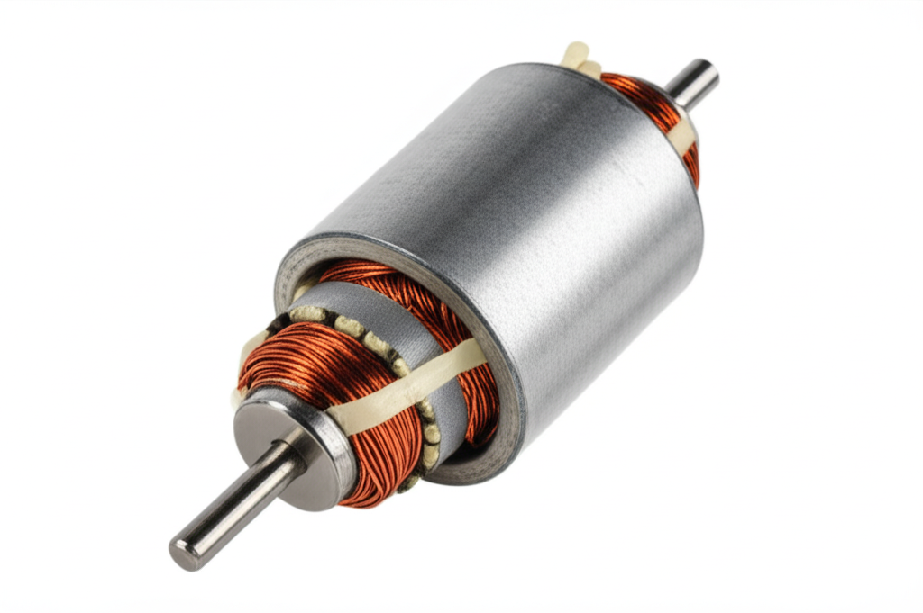
- Rotor or Armature: The rotating core that carries the armature windings. It is built from a stack of insulated laminations pressed on a shaft with precise slots for windings. The geometry of the rotor core lamination sets slot fill, leakage, and cogging tendencies.
- Commutator: Segmented copper ring attached to the armature windings. It connects coils to the brushes at the right mechanical angle for commutation.
- Carbon Brushes: Stationary conductive blocks that ride on the commutator. They complete the circuit and also filter arcing to a degree depending on composition.
- Shaft and Bearings: Support rotation while handling radial and axial loads. Bearing selection sets noise and lifespan. Proper lubrication and seals protect against dust and moisture.
- Housing and End Bells: Provide alignment, heat paths, and environmental protection. End bells locate the brushes and hold the brush springs. Alignment drives noise and wear.
A word on insulation and slot liners. Insulation materials and class ratings protect windings from abrasion and heat. Class F systems operate up to 155°C on the insulation which matches many specifications for small industrial motors. System design should consider hot spots near commutation and in the end turns.
Laminations in Practice
- Material: Most brushed DC motors use non‑oriented silicon electrical steel with insulation coatings between sheets. Coatings block eddy currents and improve punchability. Higher silicon content lowers core loss and raises resistivity at some cost to saturation flux density.
- Thickness: Common thicknesses range from 0.5 mm down to 0.35 mm for small motors. Thinner sheets reduce eddy currents at higher frequencies and at PWM switching harmonics which cuts heat and improves efficiency. They add cost and handling complexity.
- Stack construction: Interlocking features, bonding, or rivets hold stacks tight. Tight stacks reduce vibration and acoustic noise. Bonded stacks can lower interlaminar loss and boost rigidity.
If you are specifying or sourcing laminations, learn the basics of electrical steel laminations and how coatings, thickness, and alloy content move the efficiency needle.
Types of Brushed DC Motors and When to Use Them
You have four common DC motor types in the brushed family. Each type handles torque, speed, and control differently which matters for your duty cycle.
- Permanent Magnet DC (PMDC): The stator uses permanent magnets. These are the go‑to for toys, hobby motors, small appliances, and many automotive actuators. They offer compact size, good starting torque, and simple speed control with voltage or PWM.
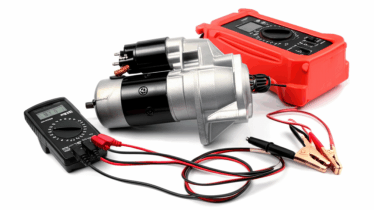
- Series Wound: The field winding is in series with the armature. Starting torque is very high which suits heavy startup loads. Speed runs away at no load which requires care. You will see these in some power tools and starter motors.
- Shunt Wound: The field winding is in parallel with the armature. Speed regulation is better under changing load. Torque at low speed is lower than a series motor. These show up in applications that need steadier speed.
- Compound Wound: Combines series and shunt fields. You get a blend of high starting torque and improved speed regulation. This is a flexible choice for variable load machines.
You can also add a gearbox for torque multiplication at lower RPM. That is common in robotics, seat adjusters, and small pumps. Gearboxes add backlash and noise so size them thoughtfully.
Control and Performance Basics: Voltage, PWM, and H‑Bridges
Control can stay simple which is why brushed DC motors dominate low‑cost motion.
- Voltage control: Speed is roughly proportional to terminal voltage minus drops. A lab supply and a potentiometer can show the trend in seconds.
- PWM (Pulse Width Modulation): Use PWM to vary effective voltage with low loss. PWM introduces current ripple and high‑frequency harmonics that can increase core loss in laminations. Good filtering and appropriate switching frequency limit those effects.
- H‑bridge control: An H‑bridge flips polarity for forward and reverse and enables braking modes. Microcontrollers can drive H‑bridges directly or through gate drivers. You rarely need complex vector control here which saves system cost.
- Feedback control: Add tachometers, Hall sensors, or back‑EMF sensing if you need tighter speed or position control. Servo motors often start with a brushed DC core and a feedback loop for precise actuation.
Electrical parameters matter. Resistance sets I²R loss. Inductance shapes current ripple and transient response. Back EMF constant links speed to voltage. You can model this with a simple RL circuit and a mechanical load model which gives you a solid first‑order prediction.
EMI is real. Brush arcing generates broadband noise and sparks. Snubbers across the terminals, RC networks on brushes, ferrite beads, and proper grounding reduce emissions. Shielding and twisted pair wiring help in sensitive systems. You still need to test against EMC standards for your market.
Advantages and Disadvantages You Can Bank On
Strengths first.
- Simplicity and cost: The motor is easy to manufacture and the control electronics stay simple. Procurement sees unit prices that are tough to beat for small to mid‑size motors.
- Control: Speed control with voltage or PWM is straightforward with low overhead.
- Torque: Excellent starting torque and smooth low‑speed behavior. You can crawl at low RPM with authority which helps in robotics and actuators.
- Robustness: For many environments, these motors run for years with basic care.
Now the trade‑offs.
- Maintenance and lifespan: Brushes and commutators wear. You will plan replacements or accept finite life. Expect 1,000 to 3,000+ hours in many small motors with huge variance by load, speed, and quality.
- Efficiency: Typical efficiency lands between 60% and 80% in practical units. Small cheap motors can sit below that. Brushless motors often beat 85% to 90% under similar conditions.
- EMI: Arcing at brushes generates electromagnetic interference. Sensitive electronics and compliance testing will notice.
- Noise: Brushes make acoustic noise and the commutation process adds electrical noise. Brushless motors run quieter for the same power.
- Sparking: Visible sparks at the brushes can create hazards in explosive atmospheres. You avoid brushed motors in those zones unless you have protective measures and certifications.
Common Applications and What They Tell You About Fit
- Consumer electronics and appliances: Toys, electric toothbrushes, handheld vacuums, and fans leverage low cost and simple control. Unit price drives everything.
- Automotive subsystems: Power windows, seat adjusters, HVAC blend doors, and wiper motors in older platforms. The duty cycle stays intermittent which helps lifespan.
- Power tools: Budget drills, small saws, and sanders use series motors for high starting torque. They trade efficiency for cost and punch.
- Robotics and hobby projects: Entry‑level robotics kits and actuators use PMDC motors for simple integration. H‑bridge boards and microcontrollers make this plug and play.
- Industrial: Low‑cost pumps, conveyors, and fans where precision or extreme longevity is not critical. Easy maintenance and ready availability help here.
If any of those match your use case, brushed DC likely sits on your shortlist.
Brushed vs Brushless: The Key Distinction in Practice
The distinction is simple. Brushed motors use mechanical commutation through brushes and a commutator. Brushless motors use electronic commutation with a controller and a permanent magnet rotor.
Brushless motors often win on efficiency, EMI, acoustic noise, and lifespan. They need a controller that adds cost and complexity. Brushed motors win when you need to keep the control stack simple and you want strong low‑speed torque without sensor feedback. You also move faster in prototyping with brushed motors which shortens early schedules.
Lamination Materials and Manufacturing: A Practical Guide
This is the part many engineers skip then regret. Laminations govern a big slice of your core loss and set real limits on thermal performance and reliability. You have two buckets to consider: material selection and manufacturing processes.
Material Considerations
- Non‑oriented silicon steels (M‑grades): The industry workhorse for motor laminations. Silicon increases resistivity which lowers eddy currents and reduces hysteresis loss. Non‑oriented grain structure gives consistent properties in all directions which suits rotating machines. ASTM A677 covers many non‑oriented electrical steels.
- Pros: Good balance of cost, permeability, and core loss for general DC motor frequencies and PWM harmonics.
- Cons: Lower saturation flux density than plain carbon steel. Very thin gauges raise cost.
- Grain‑oriented silicon steel: Optimized for one direction which is great for transformers. It sees limited use in rotating machines because flux rotates which loses the grain‑direction advantage.
- Cobalt alloys: Higher saturation flux density and lower losses at high frequency. You see this in aerospace or high power density machines. Cost is high which limits use in commodity brushed motors.
- Coatings: Organic or inorganic insulation coatings on both sides of each lamination block eddy current paths. Coating class affects punchability, interlaminar resistance, thermal stability, and bonding. Verify coating compatibility with your bonding or varnish process.
- Thickness: Typical thicknesses for small motors range from 0.35 mm to 0.5 mm. Thinner gauges reduce eddy currents especially with higher PWM frequencies and fast switching edges. They cost more and can deform during handling which affects stack flatness.
You can explore consolidated options for motor core laminations to align alloy, thickness, and coating with your duty cycle and switching strategy.
Standards you will meet often:
- IEC 60034 for rotating electrical machines. Defines performance test methods and ratings.
- NEMA MG 1 for motors and generators. Common in North American markets.
- ASTM A677 for non‑oriented electrical steel and ASTM A683 for grain‑oriented steel. Material baseline in many specs.
Manufacturing and Assembly Processes
- Stamping: The volume champion. Tooling cost is higher up front yet per‑piece cost drops fast with volume. Stamping can add burrs which raise interlaminar shorting risk so you control burr height tightly. Dies can include interlock features for stack assembly which removes the need for welding.
- Laser cutting: Perfect for prototyping and low volume with complex geometries. No tooling lead time. Heat‑affected zones can alter magnetic properties on the cut edge especially in thin gauges. Post‑processing can mitigate this.
- Wire EDM: Excellent precision with minimal heat input. Slower and costly for volume. Great for development work where geometry is in flux.
- Waterjet: No thermal effects. Tolerances are looser than laser or EDM. Useful for very early prototypes.
- Stacking and bonding: Interlocking laminations act like LEGO bricks and create rigid cores without welding. Bonding with adhesives or resin can lower interlaminar loss further and damp vibration. Rivets or through‑bolts work yet add local stress. Welding can degrade magnetic properties near the weld due to heat so you use it sparingly.
- Skewing: Slightly skewed rotor or stator slots reduce cogging torque and acoustic noise. Skew adds manufacturing complexity and can reduce peak torque a touch.
- Impregnation and varnish: VPI or dip varnish locks windings, improves heat transfer, and raises mechanical robustness. Check resin compatibility with lamination coatings and winding insulation.
Dimensional control matters. Slot geometry sets fill factor. Stack height sets magnetic path length and back EMF. Concentricity and runout affect balance and bearing loads which drive noise and wear.
Best‑Fit Choices by Application
- High‑volume consumer motors: Choose stamped non‑oriented silicon steel with optimized interlocks. Thickness around 0.5 mm often balances loss and cost. Bonded stacks can improve noise if your brand cares about acoustics.
- Prototyping and pilot runs: Laser or EDM cuts with 0.35 to 0.5 mm gauges. Validate thermal behavior at intended PWM frequency because thinner laminations may be worth the cost if your drive switches fast.
- High torque low speed robotics: PMDC with skewed rotor slots and bonded stacks to cut cogging and whine. Pair with an H‑bridge and PWM around a few kHz to balance switching loss and audible noise.
- Power tools: Series wound motors with rugged stamped laminations. Accept higher core and copper loss for torque density. Control brush grade and commutator quality to handle arcing under fast starts.
- Automotive actuators: PMDC with tight dimensional control on the armature stack and low‑friction bearings. EMI countermeasures at the terminals and good cable routing to protect nearby ECUs.
Specification, Sizing, and Reliability Fundamentals
You can size a brushed DC motor with a few practical relationships.
- Torque (T) ≈ kT × I. The torque constant kT links current to torque. It depends on magnet strength, winding turns, and geometry.
- Speed (ω) ≈ (V − I × R − drops)/kE. Back EMF constant kE links speed to voltage. Units line up with your system model.
- Power (Pout) = T × ω. Efficiency = Pout/Pin with Pin = V × I. Subtract copper, core, mechanical, and stray losses.
- Thermal limits: Insulation class sets hot spot limits. Class F systems target 155°C. Laminations and varnish aid heat spread to the housing which limits temperature rise.
Check mechanical items early.
- Bearings: Choose type and lubrication for your load and life target. Sleeve bearings cost less and can be quiet at low speed. Ball bearings handle higher loads and longer duty cycles.
- Shaft and fits: Press fits, runout, and concentricity affect balance and vibration. A well‑balanced armature protects bearings and lowers noise.
Rating labels and datasheets will list voltage, no‑load speed, stall torque, resistance, and sometimes inductance. Measure your specific unit if control precision matters because tolerances add spread.
Maintenance and Troubleshooting for Brushed Motors
Brushed motors love simple care.
- Brush wear: Brushes shorten over time. Replace when the length reaches the manufacturer’s minimum. Weak springs cause arcing and poor commutation which accelerates wear.
- Commutator wear: Look for grooving, raised mica, or pitting. Light resurfacing and undercutting can recover performance in serviceable units. Keep care within the OEM guidance.
- Sparking and EMI: Excessive sparking points to worn brushes, contamination, or timing issues. Clean dust and check brush grade. Add or tune snubbers and filters if EMC testing flags problems.
- Overheating: Verify load torque and duty cycle. Check airflow and housing conduction. High PWM frequency can raise core loss in laminations which pushes temperature up. Move switch frequency or change lamination thickness if needed.
- Noise: Mechanical rattle often traces to bearing wear or loose stacks. Electrical whine can be PWM related. Adjust PWM strategy or switch to skewed laminations.
A simple checklist during maintenance prevents most surprises.
Typical Data and Benchmarks You Can Expect
These ranges align with common industry experience for small to mid‑size brushed DC motors. Actual numbers depend on design, materials, duty cycle, and cooling.
- Efficiency: 60% to 80% for typical designs. Brushless often clears 85% to 90%.
- Operational lifespan: 1,000 to 3,000+ hours for brushes and commutator under moderate loads. High‑end designs under lighter duty can exceed that. Brushless often runs 10,000 to 20,000 hours or more.
- Relative cost: Small to mid‑size units land around $1 to $50 for many industrial or hobby uses. Control electronics stay simple which lowers system cost.
- Maintenance: Plan for brush inspection and replacement. Keep the commutator clean.
- EMI: Moderate to high without mitigation. Add snubbers and shielding for sensitive environments.
- Noise: Moderate due to brush contact and vibration. A bonded or interlocked lamination stack helps here.
- Speed control: Voltage or PWM control is direct and efficient enough for most use cases.
- Low‑speed torque: Strong starting torque allows heavy loads from a standstill.
- Operating temperature: Up to about 155°C for Class F systems. Good thermal paths and conservative duty cycles widen your margin.
These are starting points. Always validate with your intended load and environment.
Standards, Compliance, and Documentation
- Electrical performance and testing: IEC 60034 and IEEE Std 112 define methods and terms for motor performance. Use them as your common language across suppliers.
- Mechanical and dimensional: ISO tolerances apply to fits and stack geometry. Your drawing should call out burr limits and stack flatness for laminations.
- Materials: ASTM A677 for non‑oriented electrical steel and ASTM A683 for grain‑oriented steel. These anchor material requirements. Coating specs should reference recognized classes.
- EMC and safety: CISPR 11 or CISPR 14 for emissions depending on product type. UL and CE requirements apply by market and product category. Brushed motors bring sparks so hazard‑rated environments require special designs and certifications.
Document your lamination material, thickness, coating, stack process, and inspection method. That keeps procurement honest and production stable.
Your Engineering Takeaway
- Brushed DC motors deliver cost‑effective torque with simple control. You can move quickly with them which helps schedules and budgets.
- Laminations are not a detail. Thickness, alloy, and coating drive core loss, heat, and EMI behavior under PWM. Treat them as a primary design variable.
- Choose your motor type for the job. PMDC for simple actuators. Series wound for punchy starts. Shunt or compound for steadier speed.
- Basic control works. Voltage or PWM through an H‑bridge gets you far. Add feedback only when your tolerance needs it.
- Plan for maintenance. Brushes and commutator wear set service intervals. EMI mitigation and thermal design prevent headaches.
If you are defining the magnetic stack or updating a spec, review lamination choices and stack construction first. Learn the options for stator core lamination, rotor core lamination, and the broader landscape of motor core laminations as well as common electrical steel laminations. Then align your PWM strategy, duty cycle, and insulation class with your thermal targets.
Actionable next steps:
- Define your duty cycle and load torque across the operating range. Set thermal and acoustic targets early.
- Pick a lamination thickness and material that matches your switching frequency and efficiency goals. Validate with core loss data from the supplier at your excitation levels.
- Choose a stack assembly method that supports your noise and rigidity goals. Interlock or bonding often pays back quickly.
- Prototype with your intended H‑bridge, PWM frequency, and filtering. Measure temperature rise and EMI with real wiring and enclosures.
- Lock in standards and inspection methods on the drawing. State coating class, burr limits, interlaminar resistance checks, and stack flatness.
When you do those five things, brushed DC motors stop being a compromise. They become a clear, defensible engineering decision with reliable performance and predictable cost.