What is a Shunt Wound Motor? Understanding its Design, Working, and Applications
When you’re designing machinery that requires consistent speed under varying loads—think machine tools, conveyors, or certain types of fans—choosing the right motor is paramount. The wrong choice can lead to inefficient operation, poor performance, and even equipment damage. Among the classic workhorses of the electric motor world, the shunt wound DC motor stands out for its exceptional speed regulation.
But what exactly is a shunt wound motor, and how does it achieve this remarkable stability? Understanding its design and operating principles is key to leveraging its strengths in your applications. This guide will break down the essential concepts, from its core components to its unique performance characteristics, helping you determine if it’s the right solution for your engineering challenge.
In This Article
- What is a Shunt Wound Motor? A Clear Definition
- Core Components and Construction: A Look Inside
- How a Shunt Wound Motor Works: The Principle of Operation
- Key Characteristics of Shunt Wound Motors
- Advantages: Why Choose a Shunt Motor?
- Disadvantages and Limitations to Consider
- Common Applications: Where Shunt Motors Shine
- Shunt vs. Series vs. Compound: A Quick Comparison
- Conclusion: The Enduring Role of Shunt Wound Motors
What is a Shunt Wound Motor? A Clear Definition
A shunt wound DC motor, often simply called a shunt motor, is a type of self-excited direct current (DC) motor. Its defining feature is that its field winding is connected in parallel, or “in shunt,” with its armature winding.
Think of it like a plumbing system with two parallel pipes. The main electrical current from the power source splits, with some of it flowing through the armature (the rotating part that does the work) and the rest flowing through the field winding (which creates the magnetic field). This parallel connection is the secret to its most prized characteristic: excellent speed regulation. Unlike other DC motor types that can drastically speed up or slow down as the load changes, a shunt motor maintains a relatively constant speed from no-load to full-load conditions.
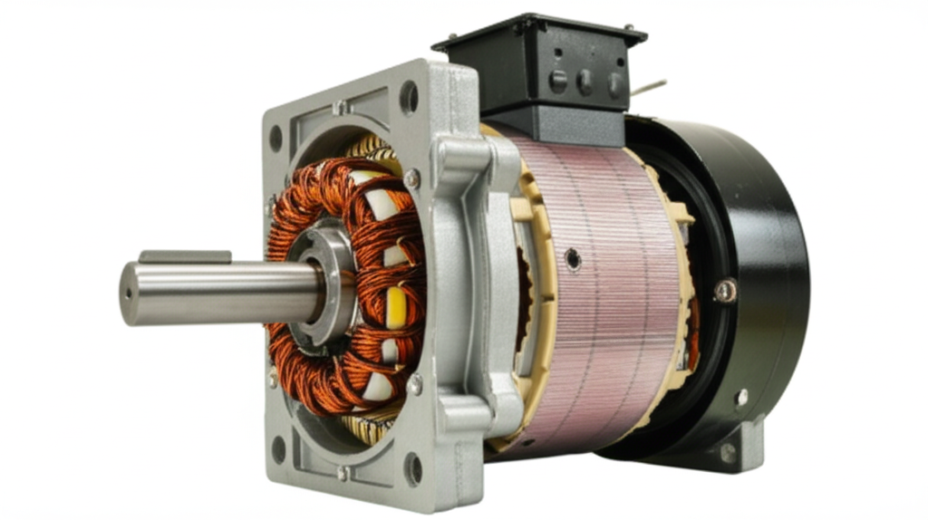
Core Components and Construction
At a glance, a DC shunt motor looks similar to other brushed DC motors. However, the internal wiring and the properties of its windings are what set it apart. Let’s break down the key components.
(Note: A simple circuit diagram showing the parallel connection of the armature and field winding would be placed here.)
- Stator (Field Assembly): This is the stationary part of the motor that houses the field windings.
- Yoke: The outer frame of the motor, typically made of cast iron or steel. It provides mechanical support and completes the magnetic circuit.
- Field Winding: This is the coil of wire wrapped around the stator’s pole pieces. In a shunt motor, this winding is made of many turns of fine wire, giving it a high resistance. When current flows through it, it creates a strong, stationary magnetic field.
- Rotor (Armature Assembly): This is the rotating part of the motor.
- Armature Core: Built from thin, stacked layers of high-grade electrical steel laminations, the core is designed to minimize energy losses from eddy currents. The quality of this core is critical for motor efficiency. The individual plates in the rotor core lamination stack are insulated from each other to break up the paths of these wasteful currents.
- Armature Winding: This consists of copper coils housed in slots on the armature core’s surface. This is where the main work-producing current flows.
- Commutator and Brushes: This is the ingenious mechanism that allows a DC motor to rotate continuously.
- Commutator: A segmented copper ring attached to the armature shaft. It reverses the direction of the current in the armature coils at precisely the right moment in each rotation.
- Brushes: Usually made of carbon, these stationary blocks press against the rotating commutator segments, conducting electrical current from the power supply to the armature winding. The brushes and commutator are the primary wear components in a brushed DC motor and require periodic maintenance.
- Shaft and Bearings: The central shaft transmits the motor’s mechanical power to the load, supported by bearings that allow it to spin freely with minimal friction.
How a Shunt Wound Motor Works: The Principle of Operation
Understanding the shunt motor’s operation comes down to two key concepts: the motor principle and the effect of its unique parallel wiring.
1. The Basic Motor Principle (Fleming’s Left-Hand Rule)
Like all DC motors, the shunt motor operates on the principle of the Lorentz Force. When a current-carrying conductor (the armature winding) is placed in a magnetic field (created by the field winding), it experiences a force. This force creates the turning motion, or torque, that spins the rotor. The direction of this force is governed by Fleming’s Left-Hand Rule.
2. The “Shunt” Connection and its Impact
Here’s where it gets interesting. The field winding is connected in parallel with the armature winding across the DC power supply. This simple design choice has profound consequences:
- Constant Field Strength: Because the field winding is connected directly across the supply voltage, the current flowing through it (the field current, If) is largely independent of the armature current (Ia). Since the field current is what generates the magnetic field, the magnetic flux (Φ) remains practically constant, regardless of the load on the motor.
- The Role of Back EMF: As the armature begins to rotate within the magnetic field, it acts like a small generator. It induces a voltage in its own windings that opposes the main supply voltage. This is called Back Electromotive Force (Back EMF or Eb). Think of it as an internal, self-regulating brake. The faster the motor spins, the greater the Back EMF it generates.
3. Self-Regulating Speed
This relationship between Back EMF and speed is what gives the shunt motor its fantastic speed regulation. Here’s how it works:
The entire process happens almost instantaneously. The result is a motor that stubbornly resists changes in speed, dropping only slightly as the load increases from zero to its full rated capacity.
Key Characteristics of Shunt Wound Motors
The unique design of the shunt motor gives it a distinct set of performance characteristics that engineers can leverage.
Speed-Torque Characteristics
The most important characteristic is its speed-torque curve. If you plot the motor’s speed against the torque it’s delivering, you’ll find the line is almost flat. There is a slight, linear drop in speed as the load (and thus torque) increases, typically only about 5-10% from no-load to full-load. This makes it a “constant speed” motor, ideal for applications where maintaining a set RPM is critical.
Speed Control
One of the great historical advantages of DC motors is their straightforward speed control. The shunt motor offers several effective methods:
- Weaker Field (Higher Resistance): Reducing the field current weakens the magnetic flux (Φ). To generate the same Back EMF, the motor must spin faster. This is used for speeds above the motor’s base rated speed. Caution is needed, as excessive field weakening can lead to dangerously high speeds and instability.
- Stronger Field (Lower Resistance): Increasing the field current strengthens the magnetic flux, causing the motor to slow down.
Starting Torque
The shunt motor provides a moderate starting torque, typically around 150% of its full-load torque. Because the field flux is constant and at its maximum at startup, the starting torque is directly proportional to the armature current. While it’s not as high as a series motor (which can produce starting torques up to 500% of full load), it’s more than sufficient for applications that don’t start under heavy load, such as fans, pumps, and machine tools.
Efficiency
Shunt wound motors are generally efficient, often operating in the 75-90% range depending on their size and design. The main losses are copper losses (I²R heating in the armature and field windings), iron losses (hysteresis and eddy currents in the core), and mechanical losses (friction and windage). The constant field loss is a drawback at very light loads, but efficiency is typically excellent near the motor’s rated operating point.
Advantages of Shunt Wound Motors
- Excellent Speed Regulation: This is its hallmark. It maintains a nearly constant speed from no-load to full-load.
- Precise Speed Control: Speed can be controlled accurately both above and below the base speed, especially with modern electronic drives.
- Self-Limiting Speed: Unlike a series motor, which can theoretically “run away” to destructive speeds if its load is suddenly removed, a shunt motor’s speed is inherently limited by its back EMF.
- Smooth and Quiet Operation: The consistent torque delivery results in smooth and relatively quiet performance.
Disadvantages of Shunt Wound Motors
- Moderate Starting Torque: It’s not suitable for applications requiring very high starting torque, such as electric traction (trains, trams) or heavy-duty cranes.
- Requires a DC Power Supply: In an AC-dominated world, this often necessitates a rectifier or a dedicated DC power source, adding complexity and cost.
- Maintenance: The carbon brushes and commutator are subject to wear and require regular inspection and replacement, making them less suitable for inaccessible or maintenance-free applications compared to AC induction or brushless DC (BLDC) motors.
- Cost and Complexity: Compared to the ubiquitous and robust AC squirrel cage induction motor, the brushed DC motor is more complex and often more expensive to manufacture.
Common Applications of Shunt Wound Motors
Given their characteristics, shunt motors have carved out a niche in applications where speed stability is the most important factor.
- Machine Tools: Lathes, milling machines, grinders, and drill presses all rely on a consistent cutting speed for a clean finish and dimensional accuracy.
- Fans, Blowers, and Centrifugal Pumps: These applications often require a constant flow rate, which is directly related to the motor’s speed.
- Conveyor Systems: Shunt motors are used for conveyors that need to maintain a steady transport speed regardless of the weight of the items being moved.
- Printing Presses & Textile Machinery: The need for precise, consistent speed to ensure quality in printing and weaving processes makes the shunt motor a good fit.
- Generators (Dynamos): When driven by a prime mover, the shunt machine’s architecture works excellently in reverse. A shunt generator has good voltage regulation, making it historically important for battery charging and DC power systems.
Shunt vs. Series vs. Compound: A Quick Comparison
To fully appreciate the shunt motor, it’s helpful to see how it stacks up against its DC motor siblings.
| Feature | Shunt Wound Motor | Series Wound Motor | Compound Wound Motor |
|---|---|---|---|
| Windings | Field in parallel with armature | Field in series with armature | Both a series and a shunt field winding |
| Speed Regulation | Excellent (nearly constant speed) | Poor (speed varies greatly with load) | Good (a compromise between shunt and series) |
| Starting Torque | Moderate (~150% of full load) | Very High (up to 500% of full load) | High (higher than shunt, lower than series) |
| No-Load Speed | Stable and predictable | Dangerously high (can self-destruct) | Stable (limited by shunt field) |
| Best For | Lathes, fans, pumps, conveyors | Traction (trains), cranes, hoists, starter motors | Rolling mills, presses, shears, elevators |
Essentially, the choice depends on the application’s core requirement: constant speed (shunt), massive starting torque (series), or a blend of both (compound).
Conclusion: The Enduring Role of Shunt Wound Motors
In an era dominated by AC induction motors with variable frequency drives (VFDs) and sophisticated brushless DC motors, it might seem like the classic shunt wound DC motor is a relic. While its market share has certainly decreased, it’s far from obsolete. For applications demanding straightforward, reliable, and inherent speed stability without the complexity of advanced electronics, the shunt motor remains a viable and effective solution.
Its principles are a cornerstone of electrical engineering, demonstrating the elegant relationship between magnetic fields, current, and mechanical motion. Whether you’re maintaining legacy industrial machinery or designing a new system where precise speed control is key, understanding the unique characteristics of the shunt wound motor is a valuable tool in any engineer’s arsenal. The design of its core, often using high-quality motor core laminations, is a testament to the enduring principles of efficient electromagnetic design.