What Is a Stator on a Motor? Understanding Its Core Role and Function
If you design, specify, or source electric motors, you care about efficiency, torque density, acoustic noise, and reliability. All roads lead back to the stator. It’s the stationary heart of every electric motor and generator, and it sets the ceiling for performance and cost. If you’ve wondered what a stator actually is, how it works, and how materials and manufacturing choices affect outcomes, you’re in the right place.
You face a tight set of trade-offs. Higher efficiency vs. material cost. Power density vs. thermal limits. Precision vs. lead time. The stator sits at the center of these decisions since its core laminations and windings create the magnetic field that drives the rotor and sets the stage for torque, speed, and losses.
Let’s unpack what matters, why it matters, and how to pick the best path for your application.
In This Article
- Why the Stator Matters and What You’re Solving
- Stator Basics: Definition, Components, and Motor Context
- Engineering Fundamentals: Magnetic Fields, Core Losses, and Torque
- Material Considerations for Stator Laminations
- Manufacturing and Assembly Processes That Move the Needle
- Matching Solutions to Your Application
- Performance, Testing, and Maintenance Essentials
- Cost, Reliability, and Procurement Considerations
- Key Takeaways and Next Steps
Why the Stator Matters and What You’re Solving
Problem
- “What is a stator on a motor?” You need an answer that goes beyond a textbook definition. You need to see how stator choices ripple through efficiency, torque, power output, noise, and lifetime.
- “How does lamination thickness affect motor efficiency?” Thinner laminations reduce eddy current loss and heat, which boosts efficiency and reliability. They can raise material cost or complexity though.
- “What material is best for a high-frequency application?” Grain-oriented or high-grade non-grain oriented electrical steels can help. So can cobalt alloys in extreme cases. Cost changes quickly.
- “What winding style should I consider?” Round wire vs. hairpin windings affects fill factor, thermal paths, and manufacturability. Your stator slot, teeth, and insulation system must match the plan.
You’re balancing performance targets with procurement realities. The stator is your lever. Get it right and the rotor follows.
Stator Basics: Definition, Components, and Motor Context
Definition
- A stator is the stationary part of an electric motor or generator. It houses a laminated iron core and copper windings that create a magnetic field. In a generator this is where electrical energy is induced and collected. In a motor this is where the magnetic field begins.
Stator vs. rotor
- The stator is fixed. The rotor spins. The stator produces a stationary or rotating magnetic field that interacts with the rotor field to generate torque. That’s the core of motor theory.
- For clarity on component specifics, see the difference between stator core lamination and rotor core lamination techniques since both stacks work together as a magnetic circuit.
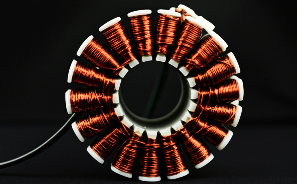
The anatomy of a stator
- Stator core: A stack of thin electrical steel laminations (silicon steel) with slots and teeth. Laminations are insulated from each other which reduces eddy current loss. The core concentrates magnetic flux and provides a low-reluctance path in the magnetic circuit.
- Windings: Copper wire coils placed in stator slots. The wire often uses enamel insulation. The end turns extend beyond the core as stator end windings. In EV designs you may see hairpin or bar windings for a higher slot fill factor and improved cooling.
- Frame or housing: A rigid shell that supports the core and windings. It also helps with heat dissipation and mounting. In pump motors, HVAC fans, and compressors you’ll see different frames but the job is the same.
- Insulation system: A layered system that includes slot liners, tapes, varnish, epoxy resin, or full epoxy encapsulation. The goal is to prevent interturn shorts and ground faults and to protect the windings from heat, vibration, and contamination.
- Accessory components: Slot wedges to retain coils, phase separators, lacing, and sometimes thermistors or RTDs for temperature monitoring.
Where you find stators
- AC induction motors, synchronous motors, and single-phase or three-phase motors.
- DC motors with permanent magnet stators or field windings.
- Brushless DC (BLDC) motors that place permanent magnets on the rotor and windings on the stator.
- Generators and alternators in industrial machinery, wind turbines, and automotive alternators.
Key terms you’ll run into
- Stator poles, stator slots, stator teeth, magnetic flux, rotating magnetic field, back EMF, stator current, stator voltage, impedance, inductance, resistance, and torque. Each connects back to the magnetic field the stator builds and how it drives the rotor.
Engineering Fundamentals: Magnetic Fields, Core Losses, and Torque
How a stator creates torque
- Run current through the stator windings and you produce a magnetic field. In a three-phase AC motor the stator currents are phase shifted so the field rotates around the air gap. The rotor chases this rotating field which produces torque.
- In induction motors the rotor slips slightly behind the stator’s rotating magnetic field which allows current to be induced in the rotor bars. That interaction produces torque.
- In synchronous motors the rotor field locks in step with the stator’s rotating field. You can use rotor windings or permanent magnets to create the rotor field.
- In a brushed DC motor the stator often uses permanent magnets or field windings to create a stationary field. The commutator and brushes switch rotor current to keep torque in the same direction.
- In BLDC motors you energize the stator windings in sequence. The rotor carries permanent magnets. Electronic commutation controls timing and creates smooth torque production. For BLDC-specific stacks see the design considerations in a BLDC stator core.
Analogy time
- Think of magnetic permeability like a sponge for magnetic field lines. A high-permeability stator core lets flux pass easily which supports strong torque for a given current.
- Eddy currents are like little whirlpools in a river. A changing magnetic field drives swirling currents in a solid metal core which wastes power as heat. Thin, insulated laminations break up the whirlpools so they never get big.
Core losses you must manage
- Hysteresis loss: Energy lost as the core’s magnetic domains flip direction each AC cycle. It depends on material coercivity which is the resistance to demagnetization, and on frequency and flux density.
- Eddy current loss: Energy lost due to those circulating currents in the core. It rises dramatically with thickness and frequency. Thinner laminations with good insulation reduce it.
- Stray load loss: Residual losses tied to geometry, harmonics, and assembly.
Why lamination thickness matters
- Thinner laminations cut eddy current loss. Upgrading a stator core from a thicker electrical steel to a finer gauge can reduce core loss by 15–30% which can drive 1–3% overall motor efficiency gains based on industry reports from electrical steel suppliers and efficiency programs. That’s not a rounding error. It can mean smaller heat sinks, cooler windings, and longer insulation life.
The rotating magnetic field at a glance
- In a three-phase stator, windings spaced 120 electrical degrees apart create a rotating magnetic field when energized by a three-phase current. The speed of that field is set by supply frequency and the number of poles. More poles mean lower synchronous speed for a given frequency. That detail helps with pump and fan applications where speed and torque requirements vary.
Electrical connections that shape behavior
- Wye vs. Delta connections change phase voltage and current relationships. For a fixed line voltage a Wye connection can reduce phase voltage which helps manage insulation stress during startup. Delta can deliver higher starting torque in some designs. Your stator windings and insulation class must align with the chosen connection.
Stator current, voltage, and back EMF
- The stator voltage drives current through the winding impedance. The magnetic field induces back electromotive force (back EMF) which opposes the supply. Back EMF rises with speed which is why unloaded motors draw less current once up to speed. Understanding that relationship helps with drive selection and protection settings.
Vibration and noise
- Slot/pole combinations influence cogging torque and electromagnetic vibration. Skewing laminations or rotor bars and optimizing slot geometry can reduce acoustic noise. If you source motors for HVAC systems or compressors you know how important this can be in tight noise specifications.
Material Considerations for Stator Laminations
Your choice of electrical steel sets the baseline for core loss, saturation, and cost.
Electrical steels
- Non-grain oriented (NGO) silicon steels are the workhorse. They offer good magnetic properties in all directions which suits motors and generators where flux rotates. You’ll hear M-grades in North America which relate to core loss at a test condition.
- Grain-oriented (GO) silicon steels have superior properties along the rolling direction which suits transformers. A motor’s rotating flux path reduces the benefit though. Some special synchronous machines use GO steel carefully oriented in tooth-yoke regions, but this is uncommon.
- Higher silicon content reduces core loss and increases resistivity. That’s good for eddy current reduction. It can make the steel harder which affects stamping and burr formation.
Where to dive deeper on materials
- If you want a broad overview of alloys, gauges, and their trade-offs in one place, explore electrical steel laminations as a starting point.
Premium and specialty materials
- High-grade NGO steels (low core loss grades) help at elevated frequencies or when you chase IE3 or IE4 efficiency classes per IEC or NEMA standards.
- Cobalt-iron alloys push saturation flux density higher which boosts torque density. Aerospace and high-speed machines use them despite higher cost.
- Amorphous metals deliver very low core loss at high frequency. They are common in transformers and some specialized high-frequency motors though manufacturing can be more complex.
Wire and insulation system
- Copper windings with enamel insulation form your stator coils. Slot liners separate copper from the core. Wedges retain coils mechanically. Varnish or vacuum pressure impregnation (VPI) bonds the winding to the stator core which improves heat transfer and vibration resistance. Epoxy encapsulation protects against moisture and shock. Insulation classes define allowable temperature rise. Manage thermal margins carefully because a 10°C rise above the rating can halve insulation life per NEMA and material supplier guidance.
Hairpin and bar windings
- EV motors often use rectangular copper “hairpins” to hit slot fill factors of 70–80% vs. 45–60% for random wound round wire. That increases power density and improves thermal conduction from copper to iron which helps with cooling. Manufacturing changes though since you must form, insert, and braze pins with tight tolerances.
Magnetic circuit geometry
- Teeth and slots define the path for flux. More slots can reduce harmonic content though it may complicate winding. Tooth width and yoke height must carry flux without saturation which depends on ampere-turns and the B-H curve of the steel.
Manufacturing and Assembly Processes That Move the Needle
Stamping vs. laser cutting
- Progressive die stamping is the volume champion. It offers low per-part cost and tight repeatability once tools are built. You must manage burrs and avoid excessive work hardening that raises local core loss.
- Laser cutting shines in prototyping, small batches, or complex geometries. It avoids tooling cost and enables fast iteration. Heat-affected zones can raise loss if you do not control parameters or if you skip post-cut stress relief.
- Waterjet cutting avoids thermal effects though it is slower. It can be useful for early development when you need geometry fidelity without metallurgical change.
Stacking methods
- Interlocking laminations snap together like LEGO bricks. You get a rigid stack without welding. This avoids heat that could hurt magnetic properties near the joint.
- Welding is robust. Manage heat input and consider post-weld annealing to recover properties if the design allows it.
- Bonding with adhesives can reduce vibration and noise because it dampens lamination motion. It also improves mechanical integrity which helps in high-speed rotors and stators with long stacks.
Annealing and stress control
- Mechanical and thermal processes leave residual stress in steel which increases core loss. Proper annealing can recover magnetic properties. Your supplier should validate this with Epstein frame tests or single-sheet testers where applicable.
Winding insertion and coil forming
- Random wound coils insert quickly which suits many industrial motors. Form-wound coils or hairpins increase slot fill and reduce variability. They require accurate slot geometry and insulation.
- Automated stator winding machines drive consistency in coil resistance and end-turn shaping. Better repeatability lowers the spread in stator inductance and impedance which helps with drive tuning.
Impregnation and curing
- VPI pulls varnish through the winding which improves thermal paths and creates a solid structure. Dip-and-bake methods can work for smaller or lower-cost motors. Epoxy encapsulation offers top protection in harsh environments at the cost of rework difficulty.
Quality control
- Measure lamination dimensions, burr height, and slot geometry. Validate stack height and squareness. Inspect insulation for damage during insertion. Test resistance and inductance phase by phase. A quick hipot and surge test catches interturn defects before final assembly.
Matching Solutions to Your Application
Not every stator needs premium steel or hairpin windings. Choose the right tool for the job.
Industrial motors for pumps, fans, and compressors
- Focus on efficiency, reliability, and noise. Standard NGO silicon steel with an appropriate gauge often hits targets. Optimize slot/pole combinations to reduce vibration. Choose Wye or Delta winding connections based on startup and line conditions. Air cooling usually suffices. Consider VFD harmonics when you set insulation and corona-resistant wire specs.
EV traction motors
- Power density and thermal limits dominate. Hairpin windings boost slot fill and heat removal. You will likely choose a low-loss NGO grade to manage core loss at higher electrical frequencies. Water jacket or oil spray cooling helps remove heat from stator end windings. Pay attention to stator tooth tip geometry and skew to control NVH under PWM drives.
BLDC motors for robotics and drones
- Compact size and precise control matter. NdFeB permanent magnets on the rotor pair with a carefully wound stator. Copper fill, back EMF constant, and stator resistance dictate torque and efficiency at your target speed. If you want to see how lamination stack choices affect small motors, scan options for a purpose-built BLDC stator core.
Generators and alternators
- The stator becomes the energy pickup. Low core loss and good thermal management maintain efficiency over a range of loads and frequencies. Pay attention to coil pitch and end winding support since mechanical vibration from the prime mover can stress connections.
High-frequency machines and aerospace
- Consider premium NGO or cobalt alloys to push flux density and reduce losses at elevated frequency. Balance the magnetic win against cost and supply chain realities. Bonded stacks and precise impregnation help in high-speed operation.
Harsh environments
- Moisture, dust, and chemicals attack insulation. Epoxy encapsulation or high-grade varnish plus sealed frames protect the stator. Temperature sensors inside end windings give you data for predictive maintenance.
Performance, Testing, and Maintenance Essentials
Performance levers you control
- Magnetic field strength: Driven by ampere-turns and magnetic circuit design. More turns increases inductance and voltage drop. Thicker wire reduces resistance but raises copper cost and slot fill constraints.
- Thermal paths: Copper-to-iron contact, impregnation quality, and frame design control temperature rise. Lower resistance and lower core loss translate to cooler operation.
- Efficiency: Cut hysteresis and eddy current loss in the stator core. Minimize winding resistance and stray losses. Match stator impedance to your drive to reduce harmonic losses.
Testing that builds confidence
- DC resistance per phase: Confirms copper cross-section and detects imbalances.
- Inductance and impedance: Validate magnetic circuit health. Compare across phases to find asymmetry.
- Hi-pot and insulation resistance: Verify insulation integrity to the core and between phases. Watch trends over time.
- Surge testing and partial discharge screening: Catch interturn shorts and insulation weaknesses before failures.
- Back EMF measurement in BLDC and PMSM machines: Confirms winding constant and rotor magnet strength.
- Vibration analysis and acoustic tests: Detect electromagnetic or mechanical issues. Slot pass frequency peaks can point to stator-rotor interaction.
- Thermal imaging during load tests: Spot hot spots in end windings or stator teeth which can indicate poor impregnation or cooling.
Real-world reliability insights
- Industry maintenance reports and IEEE/EPRI analyses attribute roughly 30–40% of electric motor failures to stator winding faults such as insulation breakdown, interturn shorts, and ground faults. Older motors can run higher. This puts insulation quality and thermal management front and center.
- Thermal aging is relentless. A 10°C temperature increase above the winding’s insulation class rating can cut insulation life in half. Watch cooling and loading to extend service life.
- Upgrading stator core laminations from commodity grades to low-loss electrical steels can reduce core losses by double digits. The overall motor efficiency boost often lands in the 1–3% range which pays back fast in continuous-duty applications.
Common stator issues and what to watch
- Winding insulation failure: Overheating, voltage spikes, contamination, and vibration can trigger interturn shorts or ground faults.
- Core damage: Excessive burrs, poor annealing, or mechanical stress raise eddy losses and heat.
- Overheating: Inadequate cooling or overloading accelerates varnish breakdown. Monitor stator current, voltage, and temperature to protect the asset.
- Noise and vibration: Poor slot/pole selection or inadequate mechanical bracing can cause audible hum and higher vibration levels. Skew and better impregnation help.
Cooling methods
- TEFC frames rely on external fans and fins. Better fin design lowers stator temperature.
- Water jacket cools the frame efficiently in EV and high-power industrial machines.
- Direct oil cooling of stator end windings removes heat where it forms which extends insulation life.
Connections and protection
- Wye or Delta affects starting current and insulation stress. Surge protection and filters mitigate VFD-induced voltage spikes that can stress insulation on long cable runs. Choose corona-resistant enamels if your application calls for it.
Cost, Reliability, and Procurement Considerations
Repair vs. replace
- For small motors below roughly 50 horsepower, replacing a failed stator or the entire motor often costs less than rewinding when you add labor, downtime, and the performance benefit of new materials. Large or critical motors still earn a proper stator rewind by specialized shops.
- If you rewind, demand high-quality slot liners, modern varnishes or epoxies, and tight process control. Validate with electrical tests after completion.
Total cost of ownership
- Material upgrades that cut core loss can pay for themselves through energy savings. A 1–3% efficiency bump adds up in 24/7 duty.
- Better impregnation reduces vibration and extends bearing life indirectly because less electromagnetic vibration translates to lower mechanical stress. That pays back in uptime.
Standards and documentation
- Reference NEMA and IEC standards for efficiency classes, insulation classes, and performance testing. UL and CE compliance may apply for end products. For materials you may see ASTM or ISO specifications for electrical steel and enamel wire.
- Ask for material certificates, lamination loss data, and winding process controls. A documented process beats a lab-only spec sheet.
Supply chain and scalability
- Progressive die stamping excels in steady, high-volume runs with predictable cost. Laser cutting enables fast iteration. If your design moves from prototype to production, be ready to switch processes and re-validate losses after tooling.
Fit for purpose
- Balance stator performance with rotor design. High-grade stator materials can be overkill if the rotor sets the loss floor. Align both sides of the magnetic circuit with your goals. If you are coordinating both stacks, a quick review of typical rotor core lamination options helps you match designs across the air gap.
Key Takeaways and Next Steps
Your engineering takeaway
- The stator is the stationary powerhouse. It creates the magnetic field that drives torque which makes it the most influential part of motor efficiency, power density, and reliability.
- Core losses come from hysteresis and eddy currents. Thinner, better-insulated laminations and low-loss electrical steel grades cut those losses and heat.
- Winding choices matter. Hairpin windings deliver higher slot fill and better heat paths in EV and high-performance motors. Random wound coils can hit cost and reliability targets in industrial machines.
- Cooling extends life. Every 10°C above the rating can halve insulation life. Design the frame, impregnation, and cooling to move heat away from end windings and stator teeth.
- Manufacturing details decide the final 5%. Burr control, stress relief, impregnation quality, and stack bonding can add up to quieter, cooler, longer-lived motors.
Your next steps
- Define your duty cycle, target efficiency class, and thermal limits. That frames your material and process options.
- Shortlist lamination grades and thicknesses that meet your frequency and flux density needs. Validate the trade-off between core loss and cost.
- Choose a winding approach that matches your slot geometry, fill factor goals, and production scale. Pair it with an insulation system that handles your voltage and environment.
- Align stator and rotor designs early. Consider both together to hit torque, NVH, and efficiency targets.
- Discuss manufacturability with a lamination supplier’s engineering team. Share drawings and performance targets so you can lock in the right material and stacking method before you commit.
If you want a concise overview of available motor stack options before you start the deep dive, scan these resources:
- A quick look at common electrical steel laminations
- Typical features and trade-offs in stator core lamination
- BLDC-specific stack needs and geometry in a BLDC stator core
- A rotor-side snapshot to pair with your stator plan: rotor core lamination
Glossary touchpoints you can reference when you talk with your team
- Stator definition and purpose: the stationary part that carries windings and creates the magnetic field
- Stator windings and coils: copper conductors that carry current
- Stator core and laminations: stacked electrical steel sheets to guide magnetic flux and reduce eddy currents
- Stator slots, teeth, poles: geometric features that set winding layout and magnetic performance
- Rotating magnetic field: the field produced in AC stators that causes rotor motion
- Back EMF: the voltage induced that opposes supply and rises with speed
- Wye and Delta: phase connection styles that affect voltage and current
- Insulation system: slot liners, varnish, and epoxy that prevent shorts and manage heat
- Core losses: hysteresis and eddy current losses inside the stator core
A final word
- Build clarity first. The best motor designs come from simple, correct principles applied with care. Choose the right stator materials and processes, validate with clean tests, and let the physics do the work.
References and standards worth consulting
- IEEE journals and conference papers on motor design, core loss measurement, and insulation aging
- NEMA MG-1 and IEC efficiency standards for motors
- Material datasheets from electrical steel and enamel wire manufacturers
- Reliability studies from EPRI and industry maintenance reports on motor failure modes
Frequently asked technical questions we covered along the way
- What is a stator? The stationary magnetic field source in motors and energy pickup in generators
- How does a stator work? It uses current in windings to create a magnetic field that interacts with the rotor to generate torque
- What’s the difference between stator and rotor? Fixed field source vs. moving part that delivers mechanical output
- Where do losses occur? In the core through hysteresis and eddy currents and in the copper through resistance and harmonics
- Which materials help most? Low-loss NGO silicon steels for most motors with cobalt alloys or amorphous metals for special high-frequency or high-density designs
- What causes stator failures? Insulation breakdown, interturn short, ground fault, overheating, and vibration related issues
- How do I test a stator? Resistance, inductance, hi-pot, surge, back EMF, vibration, and thermal imaging under load
Extra engineering notes and reminders
- Manage stator inductance and impedance to match your inverter. Lower copper loss and clean switching reduce heat and noise.
- Keep an eye on slot fill factor and end winding length. Shorter end turns reduce copper loss and improve cooling.
- Watch mechanical tolerances. Roundness and stack squareness affect air gap uniformity which affects noise and loss.
- Use skew and optimized slot/pole combinations to reduce cogging torque and acoustic noise in BLDC and PMSM machines.
- Confirm insulation class and temperature rise calculations match your environment and duty cycle.
If you want a partner who can run the trade-offs with you, involve your lamination supplier early. A short technical consultation often saves weeks in design churn. Beyond that, it builds confidence that the stator you specify will meet performance targets without surprises in cost or lead time.