What is a Wound Rotor Motor? Understanding Its Design, Operation, and Applications
Every design engineer grapples with the critical challenge of starting and controlling massive, high-inertia loads. If you’ve ever faced the problem of moving a fully loaded crane, crushing tons of rock in a ball mill, or starting a large industrial fan without causing a voltage drop that dims the lights across the entire plant, you understand the dilemma. You need immense starting torque but you can’t afford the catastrophic inrush current that often comes with it. You’re in the right place because this is the exact problem the wound rotor motor was built to solve.
For decades, this workhorse of heavy industry has provided a robust and reliable solution for applications where starting torque, speed control, and grid stability are non-negotiable. While modern alternatives exist, understanding the wound rotor motor—often called a slip ring motor—is essential for any engineer working with heavy-duty machinery. It’s a masterclass in elegant electromechanical control.
In This Article
- The Basics: Defining the Wound Rotor Induction Motor
- How a Wound Rotor Motor Works: The Principle of Operation
- Key Components: A Look Under the Hood
- Advantages: Why Choose a Wound Rotor Motor?
- Disadvantages and Limitations: The Necessary Trade-offs
- Common Applications: Where This Motor Shines
- Wound Rotor vs. Squirrel Cage Motor: A Head-to-Head Comparison
- Maintenance Considerations: Keeping the Workhorse Running
- Conclusion: The Enduring Role of Wound Rotor Motors
The Basics: Defining the Wound Rotor Induction Motor
At its core, a wound rotor induction motor is a type of three-phase AC induction motor. Like its more common cousin, the squirrel cage motor, it operates on the principle of electromagnetic induction. A rotating magnetic field in the stationary part (the stator) induces a current in the rotating part (the rotor), creating the torque that turns the shaft.
So, what makes it different? The magic is all in the rotor’s construction.
Instead of having solid, shorted-out conductor bars like a squirrel cage motor, the wound rotor motor has a set of insulated windings, much like the stator. These windings are connected in a star (Y) configuration and their terminals are not shorted internally. Instead, they are brought out of the motor’s enclosure through a set of slip rings mounted on the shaft. These slip rings, via carbon brushes, allow for the connection of an external resistance bank to the rotor circuit.
This single design choice—the ability to add external resistance to the rotor—is what gives the wound rotor motor its unique and powerful characteristics. It transforms the motor from a simple “on/off” machine into a highly controllable powerhouse, capable of delivering incredible starting torque with minimal electrical disturbance.
How a Wound Rotor Motor Works: Principle of Operation
To truly grasp why this motor is so special, let’s walk through its operation. It all starts with a fundamental motor principle: the interaction between magnetic fields.
Stator and Rotating Magnetic Field
When you apply a three-phase AC voltage to the stator windings, it creates a magnetic field that rotates at a constant speed, known as the synchronous speed. This is standard for almost all AC induction motors. This rotating magnetic field (RMF) sweeps across the rotor conductors, and this is where the wound rotor’s unique design comes into play.
The Unique Rotor Design
According to Faraday’s Law of Induction, the RMF moving past the rotor windings induces a voltage, which in turn drives a current through them. This rotor current creates its own magnetic field. The interaction between the stator’s RMF and the rotor’s magnetic field produces the torque that makes the motor spin.
Here’s the critical part: the amount of torque produced depends heavily on the magnitude and phase of the rotor current. In a standard squirrel cage motor, the rotor’s resistance and reactance are fixed, so you get what you get. But with a wound rotor motor, you have an ace up your sleeve: the external resistor bank.
Think of the external resistance as an adjustable throttle for the motor’s torque and current.
Controlling Speed and Torque
At startup, the motor is at a standstill. At this moment, the difference in speed between the RMF and the rotor is at its maximum, leading to the highest induced voltage in the rotor. By connecting a large external resistance to the rotor circuit via the slip rings, you can achieve two amazing things:
As the motor accelerates, the external resistance is gradually reduced in steps, either manually or automatically through a control system. This keeps the motor operating in its optimal torque-producing range throughout the acceleration phase, resulting in an incredibly smooth and powerful start. Once the motor reaches its normal operating speed, the external resistors are completely shorted out and the motor behaves like a standard induction motor.
This same principle allows for variable speed control. By leaving some resistance in the rotor circuit during operation, you can increase the motor’s “slip” (the difference between the synchronous speed and the actual rotor speed), effectively reducing its running speed.
Key Components of a Wound Rotor Motor
Understanding the parts is key to understanding the whole machine. While it shares some components with other motors, a few key elements set it apart.
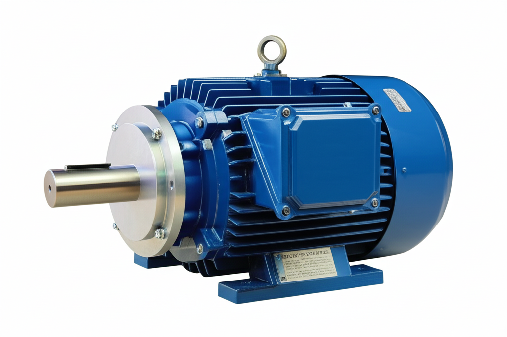
Stator
The stator is the stationary outer part of the motor. It consists of a laminated steel core with slots that house insulated copper windings. When energized by a three-phase AC supply, these windings produce the rotating magnetic field. The construction of the stator and rotor is foundational to the motor’s operation.
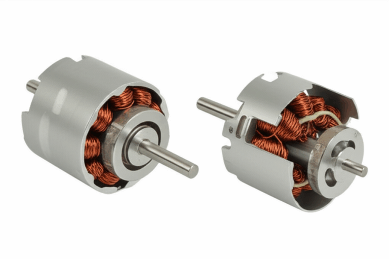
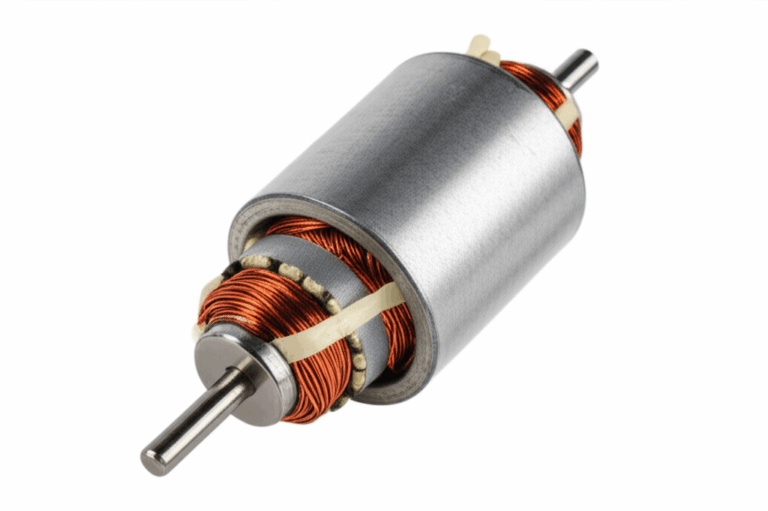
Rotor
This is the heart of the motor’s unique functionality. The rotor is the rotating component mounted on the shaft. Unlike the simple, rugged design of a squirrel cage rotor, a wound rotor is constructed with a laminated core and insulated windings, similar to the stator. These windings are carefully configured to match the number of poles in the stator. The quality of the motor core laminations used in both the stator and rotor is crucial for minimizing energy losses and ensuring high efficiency.
Slip Rings
Usually made of a copper or brass alloy, slip rings are conductive rings mounted on the motor shaft but insulated from it. Each ring is connected to one end of the three-phase rotor windings. Their job is to provide a continuous electrical connection between the rotating rotor windings and the stationary external control circuit.
Carbon Brushes
These are blocks of conductive carbon held in place by brush holders and pressed against the slip rings by springs. The brushes are stationary and serve as the physical contact point, conducting current from the external resistor bank to the spinning slip rings and into the rotor windings. They are a wear item and a key point of maintenance.
External Resistor Bank
This is a separate cabinet or enclosure containing a set of large, high-power resistors, typically arranged in a three-phase star configuration. These resistors are designed to dissipate a significant amount of heat. The bank is connected to the brushes via heavy-duty cables. A control system, often involving a series of contactors, is used to switch different amounts of resistance in or out of the rotor circuit in timed steps, allowing for controlled acceleration and speed adjustment.
Advantages of Wound Rotor Motors
So, why would an engineer choose this more complex and expensive motor? The benefits are significant and targeted for specific, demanding applications.
High Starting Torque
This is the number one reason. The ability to develop maximum torque at zero speed is unmatched by most other AC motors. For applications like a loaded conveyor belt, a crane lifting a heavy load from a standstill, or a large mill full of material, this high starting torque is not just a nice-to-have; it’s a fundamental requirement.
Low Starting Current
By managing the rotor resistance, you can get that massive torque without drawing a punishing amount of current from the grid. This protects the power supply from voltage dips, prevents tripping breakers, and reduces stress on all upstream electrical components, from transformers to cabling. It’s a “gentle giant” approach to starting heavy loads.
Excellent Speed Control
The external resistance provides a simple and effective method for controlling the motor’s speed. While not as precise or efficient as modern Variable Frequency Drives (VFDs), it offers a robust way to adjust speed over a considerable range (often a 50% reduction from full speed). This is vital for applications like hoists that need to move at different speeds depending on the task.
Smooth Acceleration
Because the resistance can be removed from the rotor circuit in multiple steps, the acceleration of the motor can be made incredibly smooth. This gradual ramp-up reduces mechanical shock and stress on gearboxes, couplings, and the driven machinery itself, extending the life of the entire system.
Disadvantages and Limitations
Of course, there’s no perfect solution, and the wound rotor motor comes with its own set of trade-offs. This is a common motor problem for design engineers: balancing performance against complexity and cost.
Increased Maintenance
The slip rings and carbon brushes are wear components. The brushes wear down over time and create conductive dust, while the slip rings can become grooved or oxidized. This necessitates a regular inspection and maintenance schedule to clean the components and replace the brushes, adding to the operational cost and potential downtime compared to a virtually maintenance-free squirrel cage motor.
Higher Cost and Complexity
The intricate rotor windings, the slip ring and brush assembly, and the required external resistor bank and control panel make the wound rotor motor system significantly more expensive and complex than a comparable squirrel cage motor and direct-on-line starter.
Lower Efficiency at Reduced Speeds
When you use the external resistors to reduce the motor’s speed, you are essentially converting electrical energy into heat within the resistor bank. This is wasted energy. The more you slow the motor down using this method, the less efficient the overall system becomes. For applications that run at reduced speed for long periods, a VFD-controlled squirrel cage motor is often a more energy-efficient choice.
Bulkier Design
The motor itself is slightly larger than a squirrel cage equivalent, but the main issue is the space required for the external resistor bank and its control cabinet. This can be a significant consideration in space-constrained installations.
Common Applications of Wound Rotor Motors
You’ll find wound rotor motors in the most demanding corners of heavy industry, where their unique strengths are indispensable.
Heavy Industrial Machinery: Cranes, Hoists, Conveyors
These applications are the classic use case. A crane needs to lift variable loads smoothly and precisely, requiring high torque at zero and low speeds. A long, loaded conveyor belt has immense inertia and requires a powerful yet controlled start to avoid snapping the belt. The wound rotor motor excels at both.
Mining and Crushing Equipment: Ball Mills, Crushers
Ball mills and rock crushers are prime examples of high-inertia loads. The sheer weight of the grinding media and the ore requires enormous torque to begin rotation. The controlled, high-torque start of a wound rotor motor is perfect for getting these massive machines moving without damaging the mechanics or the electrical system.
Pumps and Fans
For large centrifugal pumps or fans, especially those that need to be started against a closed valve or damper (a high-inertia condition), a wound rotor motor provides the necessary starting torque. Its speed control capabilities also allow for flow or pressure regulation, though this is often done more efficiently today with VFDs.
Other High-Torque, Variable-Speed Needs
The list goes on. You’ll find them in cement mills, driving large rotary kilns; in the sugar industry, powering cane shredders; and in steel mills, operating everything from cranes to rolling mills. Any application defined by heavy loads, high inertia, and the need for controlled starting and acceleration is a potential home for a wound rotor motor.
| Feature/Metric | Typical Value/Observation | Context/Source |
|---|---|---|
| Starting Torque | Up to 300-400% of full-load torque (FLT) is achievable. | Controlled by external resistance. Essential for starting heavy loads like crushers and mills. |
| Starting Current | Can be limited to 100-200% of full-load current (FLC). | Reduces voltage sag on the power supply. Squirrel cage motors can draw 500-700% FLC. |
| Speed Control Range | Typical speed reduction of 20-50% from synchronous speed. | Achieved by varying external rotor resistance. Higher resistance increases slip, reducing speed. |
| Efficiency | Comparable to squirrel cage motors at full load (88-95%), but drops significantly (<70-80%) at reduced speeds due to energy loss in resistors. | VFDs with squirrel cage motors offer higher efficiency at partial speeds. |
| Maintenance Frequency | Higher than squirrel cage motors. Brushes require inspection/replacement every 6 months to 2 years. Slip rings may need cleaning every 2-5 years. | Direct consequence of wear parts, adding to operational expenditure and downtime. |
| Cost | 1.5x – 2.5x more expensive than a comparable squirrel cage motor. | Due to additional components (slip rings, brushes, resistor bank) and complex manufacturing. |
| Longevity | Well-maintained motors can last 20-30+ years, but wear parts have a much shorter lifespan. | Robust construction ensures long mechanical life with proper service. |
Wound Rotor vs. Squirrel Cage Motor: A Comparison
The choice between these two induction motor types often comes down to the specific demands of the application.
| Feature | Wound Rotor Motor | Squirrel Cage Motor |
|---|---|---|
| Rotor Design | Insulated windings connected to external slip rings. | Short-circuited conductor bars (aluminum or copper). |
| Starting Torque | Very high and controllable (up to 400% FLT). | Lower and fixed (typically 150-250% FLT). |
| Starting Current | Low and controllable (100-200% FLC). | Very high (500-700% FLC) unless a soft starter or VFD is used. |
| Speed Control | Inherent capability via external resistors. | Requires an external Variable Frequency Drive (VFD). |
| Maintenance | Higher; requires regular inspection of brushes and slip rings. | Very low; no brushes or slip rings to maintain. |
| Cost | Higher initial cost for the motor and control system. | Lower initial cost for the motor itself. |
| Efficiency | High at full speed, but poor at reduced speeds. | High across a wider speed range when paired with a VFD. |
| Complexity | More complex system with more components. | Simpler, more robust, and more common. |
In essence, the squirrel cage motor is simple, cheap, and reliable for general-purpose applications. The wound rotor motor is a specialized tool for heavy-duty jobs that demand performance characteristics a standard motor just can’t deliver on its own.
Maintenance Considerations for Slip Ring Motors
The reliability of a wound rotor motor hinges on a consistent maintenance program focused on its unique components.
- Regular Brush Inspection: The carbon brushes should be checked regularly for wear. They have a wear limit line, and once reached, they must be replaced to avoid damage to the slip rings. It’s also crucial to ensure they move freely in their holders and that the spring pressure is correct.
- Slip Ring Cleaning: The slip rings can accumulate carbon dust and develop a patina. They should be periodically cleaned with a non-abrasive solvent and a coarse, non-linting cloth to ensure good electrical contact. Over time, they may become grooved and require “turning” on a lathe to restore a smooth surface.
- Bearing Lubrication: Like any large motor, proper lubrication of the bearings according to the manufacturer’s schedule is critical for a long service life.
Conclusion: The Enduring Role of Wound Rotor Motors
In an era dominated by VFDs and advanced motor controls, it might be tempting to view the wound rotor motor as a relic. But that would be a mistake. While VFDs paired with squirrel cage motors have certainly replaced them in many variable-speed applications due to higher efficiency, the wound rotor motor continues to hold its ground in a critical niche.
For the most extreme high-torque, high-inertia applications, its ability to deliver immense starting torque while being gentle on the electrical grid remains a powerful and cost-effective solution. Its rugged simplicity and proven track record make it a trusted choice in industries where reliability is measured in decades.
Your engineering takeaway is this:
- When faced with starting an extremely heavy or high-inertia load, the wound rotor motor provides an unparalleled combination of high starting torque and low starting current.
- It offers a robust, built-in method for smooth acceleration and moderate speed control.
- The trade-offs are higher cost, larger footprint, and a necessary commitment to regular maintenance of the brushes and slip rings.
By understanding the unique design and operational principles of the wound rotor motor, you are empowered to make a more informed decision. You can confidently identify the scenarios where this industrial workhorse is not just an option, but the best engineering solution for the job.