What Is an Inboard Outboard Motor? An Engineer’s Guide to Lamination Choices for Marine Drives
Every engineer who touches marine products runs into the same crossroads. You need reliable propulsion and auxiliary power in a harsh environment. You want performance and quiet operation without blowing the BOM. If you’re weighing stern drive propulsion choices or planning electric or hybrid upgrades and you’re asking how motor laminations affect efficiency, heat, and durability on the water, you’re in the right place.
This guide answers the surface-level question—what is an inboard outboard motor (I/O or sterndrive)—then dives into the engineering fundamentals that determine whether your motor cores will deliver the torque, efficiency, and life you expect in freshwater or saltwater.
We’ll use simple language, clear analogies, and pragmatic trade-off tables in prose. The goal is straightforward. Build your confidence so you can pick materials and manufacturing processes that match your application and your production plan.
In This Article
- Why I/O Propulsion Matters to Engineers and Product Teams
- What an Inboard Outboard Motor Is and How It Works
- Core Losses 101: Eddy Currents, Hysteresis, and Marine Realities
- Material Choices for Marine Motor Laminations
- Manufacturing Processes and Their Impact on Performance
- Matching Materials and Processes to Marine Applications
- Alternatives Compared: PMAC, Induction, and SRM in I/O Use
- Quality, Testing, and Tolerances That Actually Matter
- Cost Drivers and a Procurement Checklist
- Maintenance and Reliability Considerations in Salt and Fresh Water
- Your Engineering Takeaway and Next Steps
Why I/O Propulsion Matters to Engineers and Product Teams
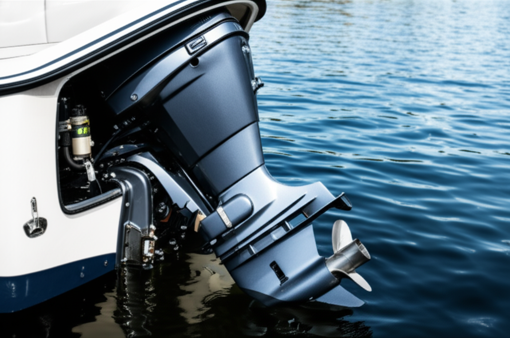
Let’s ground the problem. The modern stern drive boat sits at the intersection of performance, packaging, and customer experience. A sterndrive or inboard outboard motor puts the engine block inside the hull and hangs a steerable outdrive on the transom. The configuration keeps the transom clean which helps with swim platform space and watersports. It also allows trim and tilt for performance and draft control. For runabouts, bowriders, cuddy cabins, sport cruisers, and small yachts, I/O remains a compelling choice.
Yet propulsion is evolving. Diesel and gasoline engines still dominate I/O boats, but hybrid marine propulsion and fully electric drives are gaining ground in niche segments. Even on conventional boats, electric machines power bow thrusters, bilge pumps, trim and tilt systems, power steering, and generators. These motors live in tight compartments with heat soak, vibration, and the ever-present threat of corrosion. They need efficient cores that run cool and last.
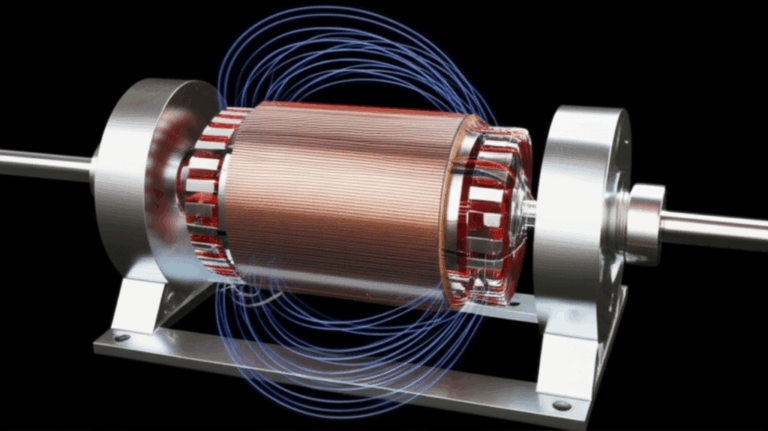
That’s where lamination engineering enters the picture. The stator and rotor cores in your BLDC, PMAC, or induction machines dictate a huge share of loss, noise, and service life. Choosing lamination thickness, grade, coating, and stack assembly will make or break your design. The physics do not care that you’re on the water.
What an Inboard Outboard Motor Is and How It Works
If you landed here with a straightforward question—what is an inboard outboard motor—here’s the concise definition you can take to your team.
- Core definition: An inboard outboard motor, also called a stern drive or I/O motor, is a hybrid marine propulsion system that combines an inboard engine with an outboard-like drive unit. The engine block sits inside the boat’s hull while the drive unit (the outdrive or lower unit) mounts outside the transom.
- Power transfer: A drive shaft runs through a transom assembly with bellows and seals, then into the outdrive gearcase which turns the propeller. U‑joints and a gimbal bearing allow the drive to pivot for steering and trim.
- Steering and trim: The outdrive pivots left and right to steer, and it trims up and down to optimize running angle or to reduce draft in shallow water. Tilt lifts the drive for storage or trailering.
- Components you’ll hear about often: Transom assembly, gimbal bearing, bellows, upper and lower gearcases, drive shaft, gearcase assembly, propeller, trim and tilt system, exhaust routing, cooling system with seawater impeller, anodes for corrosion protection, and the electrical system that ties it all together.
Why designers like I/O
- Integrated look and quiet operation since the engine lives under a hatch
- Better weight distribution than an outboard for many hulls
- Clean transom and big swim platform space for sport and family use
- Strong performance for a given footprint
Where the tradeoffs show up
- More complex service than an outboard because you have bellows, U‑joints, and a gimbal bearing
- Corrosion risk in saltwater which demands careful anode selection and antifouling practices
- Drive unit draft and potential impact damage in shallow water even when trimmed up
- Tight engine access under seats or decks which adds labor time
Popular brands and drive types you’ll see
- Mercruiser Alpha One and Bravo drives
- Volvo Penta SX and DP drives
- Gasoline engines dominate in smaller recreational boats though diesel appears in larger cruisers
If you design electric or hybrid stern drives, the physical arrangement remains the same. The outdrive still steers and trims, but you replace or supplement the inboard combustion engine with an electric motor and a reduction gear. Which brings us back to laminations and the motor core at the heart of your system.
Core Losses 101: Eddy Currents, Hysteresis, and Marine Realities
You can’t optimize a marine motor without tackling core losses. Two mechanisms dominate: eddy current loss and hysteresis loss.
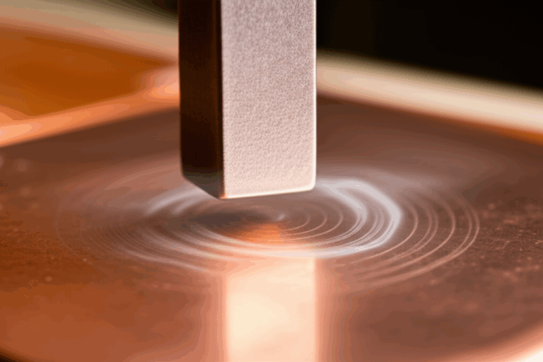
- Eddy currents: Think of these like little whirlpools in a river. A changing magnetic field induces circulating currents inside the core material. Those currents dissipate energy as heat which wastes power and raises temperature. Thinner, insulated laminations break the whirlpools into tiny eddies that lose far less energy.
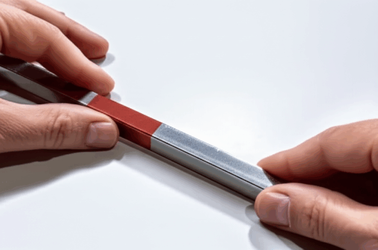
- Hysteresis: Magnetic domains inside the steel flip direction as the field cycles. That switching costs energy every cycle. Materials with lower coercivity—meaning they resist demagnetization less—have lower hysteresis loss.
Key factors you control
- Lamination thickness: Thinner sheets reduce eddy current loss, particularly at higher electrical frequencies. You’ll see common thicknesses from 0.50 mm down to 0.20 mm for high-speed machines. Thinner costs more and demands tighter tooling control.
- Insulation coating: Organic or inorganic coatings increase interlaminar resistivity which cuts eddy currents between sheets. Coating choice impacts punching quality, bonding, and corrosion resistance.
- Grade selection: Higher silicon content increases resistivity and reduces loss though it also raises brittleness. Premium oriented grades can cut losses in transformers which see unidirectional flux though motors need non-oriented grades due to rotating fields.
- Flux density and waveform: Running deeper into the B‑H curve raises hysteresis and can push the material into non-linear behavior. PWM drives add harmonic content which increases effective frequency and loss.
- Temperature: Core loss rises with temperature. Marine engine compartments often run hot after idle and slow-speed operation which can magnify loss and coating stress.
Marine specific challenges
- Saltwater brings galvanic corrosion and crevice corrosion risk. Exposed lamination edges or damaged coatings can corrode which degrades the stack and can reduce interlaminar insulation over time.
- Vibration from waves and the sterndrive gear mesh shakes everything. Loose stacks or poor bonding can fret and generate noise.
- Cooling water is plentiful which helps system design, but you must balance ingress protection, condensation, and thermal shock when you flush or rinse systems.
If you only remember one thing from this section, remember this. Lamination thickness and coating quality control your core losses and your motor’s thermal headroom. Your boat’s noise and fuel or energy consumption follow.
For background on motor core construction and its impact on performance see motor core laminations.
Material Choices for Marine Motor Laminations
Let’s walk through the most common options with their tradeoffs. You want a shortlist you can vet with your supplier and your test bench.
Silicon steel laminations (non‑oriented electrical steels)
- What it is: Low-carbon steel alloyed with silicon to increase resistivity and reduce core loss in rotating machines where magnetic flux rotates. Offered in grades sometimes designated as M‑grades or by international standards with specific loss targets at defined flux density and frequency.
- Where it shines: General purpose motors from bilge pumps to bow thrusters to I/O electric propulsion units. Good balance of cost, manufacturability, and performance in the 50–400 Hz electrical frequency range which covers many BLDC and induction machines at common speeds.
- Pros: Readily available, predictable B‑H curves, good stamping behavior, wide thickness range, coatings designed for stacking and bonding.
- Cons: Not the lowest loss material at very high electrical frequencies. Higher silicon grades can get brittle which affects punching life and burr control.
Grain-oriented silicon steel (CRGO)
- What it is: Sheet with a preferred grain direction developed during processing. It delivers very low loss along the rolling direction.
- Where it shines: Transformers with unidirectional flux. Not ideal for rotating machines because flux rotates and would see off-axis behavior. Engineers sometimes consider CRGO in axial flux machines with careful flux alignment but it stays niche for motors.
- Pros: Exceptional loss in rolling direction.
- Cons: Poor off-axis performance, limited value in rotating fields.
Non-grain-oriented silicon steel (CRNGO)
- What it is: The workhorse for motors with isotropic magnetic properties in the plane of the sheet.
- Pros: Balanced magnetic properties for rotating fields, broad grade options from commodity to high-efficiency grades.
- Cons: You still need to manage coating, thickness, and punching process to hit your loss targets.
Cobalt iron alloys
- What it is: High cobalt content alloyed steels that deliver very high saturation flux density with relatively low loss. You will see them in aerospace or high power density machines.
- Where it shines: Very high power density drives where you must squeeze torque in a small envelope or push high frequency at high flux density.
- Pros: High saturation reduces copper mass and can boost torque density.
- Cons: Expensive, tough to punch, can demand laser cutting or premium tooling which adds cost.
Amorphous and nanocrystalline
- What it is: Ribbon materials with disordered atomic structures that can exhibit very low core loss at high frequency.
- Where it shines: Power electronics magnetics and specialty high frequency motors.
- Pros: Ultra low loss at high frequency.
- Cons: Processing and mechanical properties create challenges. Less common in mainstream marine traction motors.
Corrosion and coatings that matter at sea
- Insulation classes: Inorganic phosphate coatings, organic varnishes, and hybrid systems each change punchability, bondability, and corrosion resistance. Marine designers often prefer coatings with good chemical resistance to bilge contaminants and salt mist.
- Edge protection: If lamination edges sit near salt-laden airflow or water spray, consider post-stack varnish or resin to seal exposed edges. This improves corrosion resistance and can quiet the stack.
- Standards and data: Use manufacturer loss data per standards like Epstein frame or single sheet testers which are common in electrical steel datasheets. Reference ASTM and IEC standards for coating tests and core loss measurement methods. Avoid specmanship and ask for the test method used.
If you need a quick primer on material families and their use cases see electrical steel laminations and silicon steel laminations.
Manufacturing Processes and Their Impact on Performance
Material gives you potential. Process determines whether you hit it. In marine motors, you fight loss, noise, and corrosion which puts a spotlight on burrs, heat‑affected zones, and stack integrity.
Stamping
- What it is: Progressive or compound dies punch laminations at high speed. Best for medium to high volume and proven for most motor topologies.
- Pros: Low cost per part at scale, tight repeatability, excellent edge quality when dies are well maintained. Supports interlocking features that create LEGO‑like stacks without welding which avoids heat damage to magnetic properties.
- Cons: Tooling cost and lead time. Brittle high‑Si steels and cobalt alloys can reduce tool life which raises maintenance cost.
Laser cutting
- What it is: Flexible cutting for prototypes and low volume production. No hard tooling.
- Pros: Fast iteration, complex geometries, ideal for pilot builds or frequent design changes.
- Cons: Heat‑affected zones can increase local loss which hurts efficiency. You must manage cut parameters and post‑processing like stress relief or edge finishing if the application is sensitive.
Wire EDM or fine blanking
- What it is: Precision cutting with minimal heat input for very tight tolerance needs.
- Pros: Excellent edges, minimal burrs, good for brittle materials.
- Cons: Slow and costly which makes it a niche for special rotors or test articles.
Stacking and bonding
- Interlocking: Stamped tabs snap like interlocking bricks which create strong, rigid stacks without resin or welding. Great for manufacturing speed and for maintaining magnetic properties.
- Bonding: Adhesive bonding or back‑lacquered coatings create a solid monolithic stack that reduces magnetostriction noise. It also seals edges against moisture which helps in salt environments. You must control cure to avoid squeeze‑out that changes air gaps or slot dimensions.
- Rivets and pins: Simple and effective for small stacks though they can create local stress and require care to avoid pass‑through that shorts laminations.
Welding
- Not preferred for cores. Welding introduces heat which degrades magnetic properties near the weld and can create dimensional distortion. If you must weld, minimize heat input and keep welds away from flux‑critical regions.
Tolerances and NVH
- Stacking factor: The ratio of steel to total stack thickness. Coatings and roughness reduce stacking factor which affects magnetic circuit predictions. Measure it for accurate simulations.
- Burr and flatness: Burrs increase local losses and can cut insulation which invites shorts. Flatness and squareness matter for even air gaps which control noise and efficiency.
- Impregnation: Vacuum pressure impregnation (VPI) with resin can stabilize windings and seal stacks which helps in marine condensation cycles and improves NVH.
If you want a deeper dive into specific core types and their manufacturing considerations see stator core lamination and rotor core lamination.
Matching Materials and Processes to Marine Applications
Marine applications vary wildly. The same boat can run a high‑power stern drive, sip power for instruments at anchor, and operate a thruster in short bursts near the dock. Match your lamination choices to the duty cycle and environment.
Electric stern drive propulsion
- Profile: High torque at low to mid speed with sustained operation near cruising speed. Electrical frequency tracks pole count and mechanical speed which sets your lamination thickness and grade needs.
- What to prioritize: Lower loss non‑oriented silicon steels in 0.35 mm to 0.27 mm thickness for efficiency. Premium coatings for bonding and corrosion resistance. Bonded stacks to reduce acoustic noise which customers notice in quiet electric boats.
- Cooling: Closed loop liquid cooling with heat exchangers fed by seawater keeps salt out of the motor cavity. Coat and seal cores to handle condensation and pressure washing splash.
- Corrosion: Maintain sacrificial anodes in the drive unit and manage galvanic couples across the chassis, motor housing, and gearbox. The core stack should never be a corrosion path, which argues for robust edge sealing.
Hybrid marine propulsion
- Profile: The motor assists a combustion engine during acceleration or powers low‑speed maneuvering. Duty cycles include frequent starts and variable speed.
- What to prioritize: Good part‑load efficiency and lower eddy current loss across a range of frequencies. If packaging forces higher speed to reduce gearbox ratio, move thinner in lamination thickness.
Bow thrusters and stern thrusters
- Profile: Intermittent heavy torque with limited duty cycle. Noise and vibration matter because the thruster runs during docking when people listen closely.
- What to prioritize: Bonded lamination stacks for quieter operation. Robust coatings and sealing since thrusters sit near waterline and see salt spray.
Bilge pumps and auxiliary pumps
- Profile: Long periods off, then extended operation at modest load. Reliability trumps all.
- What to prioritize: Cost-effective CRNGO grades with proven coatings and generous tolerances that keep assembly simple. Avoid over‑engineering. The pump impeller and housing drive more system‑level efficiency than shaving a few watts of core loss.
Power steering pumps and trim systems
- Profile: Intermittent or variable duty with quick response demands. Some modern boats use electric power steering which needs compact, quiet motors.
- What to prioritize: Thin laminations with low loss for smooth response. Tight tolerance on air gap for low cogging torque that keeps steering feel natural.
Generators and alternators
- Profile: Constant speed operation tied to engine speed with strong thermal loads in tight compartments.
- What to prioritize: Proven non‑oriented steels with coatings that tolerate higher temperature classes. Manage ventilation and consider VPI to stabilize windings.
Saltwater vs freshwater
- Saltwater raises the bar on coatings, seal integrity, and anodic protection. Consider more aggressive edge sealing and bonded stacks. Inspect anodes often and follow a disciplined anode replacement schedule.
Alternatives Compared: PMAC, Induction, and SRM in I/O Use
You have motor topology choices. Your lamination decisions interact with the electromagnetic design and the service environment.
Permanent magnet AC (PMAC or BLDC)
- Pros: High efficiency and power density. Excellent torque control which suits smooth docking and watersports. Compact packages help under‑hatch layouts in stern drive boats.
- Cons: Magnet cost volatility and thermal demagnetization risk. Requires careful thermal management and sealing. Laminations need low loss grades because high efficiency designs keep copper and inverter losses low which makes core loss a larger slice of the pie.
Induction motors
- Pros: Robust, magnet‑free, and proven in industrial settings. Tolerant to harsh environments and typically lower cost magnets to zero magnets.
- Cons: Lower peak efficiency and power density than PMAC in many cases. Rotor design and lamination conductivity matter since rotor bars and end rings carry losses which impact thermal limits.
Switched reluctance motors (SRM)
- Pros: Simple, robust construction without magnets or rotor windings. High temperature tolerance and good efficiency at certain operating points.
- Cons: Acoustic noise and torque ripple can be challenging in quiet marine cabins. Advanced control helps yet adds complexity. Lamination quality still matters because SRM flux swings are aggressive.
For all topologies, think in terms of system cost and customer experience. A PMAC stern drive can hit stellar efficiency and low noise which delights boaters. An induction thruster can shrug off harsh cycles with simple service. An SRM bilge pump might be overkill. Let the application lead.
Quality, Testing, and Tolerances That Actually Matter
Skip the marketing gloss. These checkpoints translate directly into performance risk mitigation.
- Incoming material verification: Confirm grade, thickness, and coating type against certificates. Spot check with single sheet tester or Epstein frame data from the mill when possible. Align test conditions with your design point to avoid apples‑to‑oranges comparisons.
- Burr height control: Set maximum burr heights and enforce tool maintenance intervals. Burrs cut insulation which increases interlaminar shorts and loss.
- Stacking factor measurement: Measure actual stacking factor for your coating and process. Feed the value back into your electromagnetic model so predictions match the test bench.
- Bonding quality: Validate adhesive cure and bond line control. Use cross sections to confirm there is no squeeze‑out into slots or critical air gaps. Check vibration resistance for thrusters and I/O propulsion units that see continuous gear mesh vibrations.
- Dimensional control: Air gap, rotor concentricity, and lamination outside diameter runout all influence NVH and efficiency. Control them tightly where it matters most.
- Environmental testing: Salt fog, thermal cycling, and condensation tests reflect marine reality. Verify that coatings do not crack and that stacks do not delaminate.
Industry standards and sources
- Use IEEE and IEC standards for motor testing and efficiency measurement to define acceptance tests.
- Reference ASTM standards for coating adhesion and corrosion resistance. Do not cite generic values without test method context.
Cost Drivers and a Procurement Checklist
You own the BOM and the timeline which means you need a clear view of cost drivers.
Major cost drivers
- Material grade and thickness: Higher silicon content and thinner gauges increase cost. Cobalt alloys move you into premium territory fast.
- Tooling: Progressive dies carry up‑front cost but drop unit price dramatically at volume. Laser cutting enables fast starts but unit cost remains higher which limits scaling.
- Yield and scrap: Rotor and stator geometries with narrow webs or complex slots can push scrap rates. Nesting optimization pays back quickly.
- Coatings and bonding: Premium coatings and post‑stack impregnation add material and labor. They save money when they solve NVH, corrosion, or reliability risks.
- Quality checkpoints: Testing costs money but catching a bad batch before final assembly saves far more.
Procurement checklist you can use today
- Duty cycle and environment defined: Speed range, torque, electrical frequency, temperature, salt or fresh water, and space constraints.
- Topology chosen: PMAC, induction, or SRM with clear rationale.
- Material targets: Grade shortlist with thickness options and acceptable coating families.
- Manufacturing path: Prototype via laser or EDM, then stamping plan for volume. Interlock vs bonded vs hybrid stacking defined.
- Tolerances: Critical dimensions and burr limits documented. Stacking factor target and measurement method agreed.
- Corrosion strategy: Edge sealing and impregnation plan if needed. Anode and galvanic considerations documented at system level.
- Test plan: Core loss verification method, NVH checks, environmental tests, and acceptance criteria ready to go.
Maintenance and Reliability Considerations in Salt and Fresh Water
Even the best design fails early if maintenance is an afterthought. Keep the whole system in view.
- For electric I/O propulsion and thrusters: Inspect cooling paths, filters, and seals at the same intervals you check bellows, U‑joints, and gimbal bearings on a traditional stern drive. A clogged heat exchanger raises winding and core temperatures which shortens life.
- Corrosion control: Follow a strict anode replacement schedule and confirm you have the right alloy for your water type. Aluminum anodes often suit brackish water, zinc for saltwater, magnesium for fresh water, yet always verify with current marine guidance because alloys evolve.
- Storage and winterization: In cold climates, winterization includes draining water from the cooling circuit, protecting against condensation, and unplugging or disabling systems that could energize motors unexpectedly. For outdrives, service impellers, inspect bellows, and renew antifouling paint on the drive unit which protects against marine growth.
- Electrical system hygiene: Check battery system health and cable integrity. Poor grounding and stray currents accelerate galvanic corrosion which can attack drive components. It also risks leakage into motor housings that invites damage.
Where the Traditional I/O Story Meets Modern Motor Engineering
You now see the bridge between classic stern drive design and motor lamination engineering. The I/O layout dictates packaging, cooling options, and service access. Your motor core choices determine efficiency, thermal margins, and noise. Together they define the boat’s performance and the owner’s experience.
To go deeper on specific component families you can browse:
- The basics of motor core laminations
- Material families for electrical steel laminations
- Manufacturing notes for stator core lamination
- Rotor-specific considerations in rotor core lamination
Your Engineering Takeaway and Next Steps
Key points to remember
- The stern drive or inboard outboard motor places the powerplant inboard and the steerable outdrive on the transom. It offers clean transoms, trim control, and strong performance which explains its popularity in runabouts, bowriders, cuddy cabins, and sport cruisers.
- Electric and hybrid variants are rising which puts motor laminations under the spotlight. Lamination thickness, grade, and coating drive eddy current and hysteresis loss which set temperature and efficiency.
- Non‑oriented silicon steels are the default for rotating machines. Use thinner gauges and premium grades for higher electrical frequencies or aggressive duty cycles. Consider bonding and edge sealing for marine corrosion and NVH.
- Stamping rules at volume. Laser or EDM shine in prototyping or exotic materials. Control burrs, stack factor, and bond lines because they link directly to losses and noise.
- Match solutions to the job. Electric stern drives need low loss cores and robust cooling. Thrusters reward bonded stacks for quiet running. Pumps need cost-effective reliability.
- Set standards up front. Define dimensional tolerances, burr limits, stacking factor targets, environmental tests, and acceptance metrics so suppliers know the finish line and you avoid surprises.
Actionable next steps
- Document your duty cycle and environment in one page. Include speed, torque, electrical frequency, compartment temperature, and salt or fresh water exposure.
- Build a two‑option material plan. Pick a baseline CRNGO grade and a premium grade in a thinner gauge so you can A/B test loss and thermal headroom early.
- Choose a prototyping path. Use laser for your first articles with process settings tuned to minimize heat‑affected zones. Plan your stamping die only when electromagnetics and tolerances stabilize.
- Define your NVH and corrosion strategy. Decide if you need bonded stacks or post‑stack impregnation. Plan edge sealing where salt spray or bilge contaminants can reach.
- Align on tests. Pick core loss measurement methods, salt fog and thermal cycling protocols, and acceptance criteria before you cut metal.
If you want a second set of eyes on your lamination stack, coating choice, or manufacturing plan, set up a short technical consultation. Bring your constraints and your duty cycle. We’ll help you trade options quickly so you can lock the spec and move forward with confidence.
—
Notes and sources: The principles in this guide align with standard electromagnetic design practices and marine engineering constraints seen across IEEE literature, electrical steel producer datasheets that report loss via Epstein frame or single sheet testers, and common marine standards for corrosion and environmental testing. Always verify material properties and core loss at your operating points with your chosen supplier because grades, coatings, and test methods vary.