What Is an Induction Motor? A Hands‑On Guide to How It Works, Why It Matters, and Where You’ll See It
Table of Contents
- Introduction: The Unsung Workhorse I Keep Coming Back To
- The Core Concept: Electromagnetic Induction Made Simple
- The Parts That Do the Work: Stator, Rotor, and the Air Gap
- Stator: Frame, Core, and Windings
- Rotor: Squirrel Cage and Wound Rotor
- The Air Gap and Other Essentials
- How an Induction Motor Works: From AC Supply to Turning Shaft
- The Rotating Magnetic Field
- Induced Rotor Current
- Torque and the Lorentz Force
- Slip and Synchronous Speed
- Types of Induction Motors You’ll Actually Meet
- Three‑Phase vs Single‑Phase
- Squirrel Cage vs Wound Rotor
- Performance, Efficiency, and Control: What Really Drives Results
- Efficiency Classes, Standards, and Power Factor
- Current, Torque, and Key Ratings
- Variable Frequency Drives and Speed Control
- Enclosures, Cooling, Duty Cycle, and Safety
- Advantages I Rely On and Limitations I Respect
- Where You’ll See Induction Motors Every Day
- Maintenance and Troubleshooting: What Has Saved Me Time and Money
- Induction vs Other Motors: Where Each One Shines
- Quick Math: A No‑Stress Example of Speed and Slip
- Selecting the Right Motor: My Practical Checklist
- The Future: Smarter Control, Better Efficiency, Same Rock‑Solid Core
- Key Takeaways
Introduction: The Unsung Workhorse I Keep Coming Back To
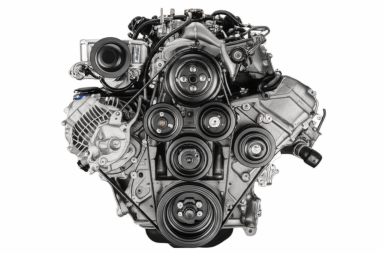
I still remember the first time I opened a tired pump motor on a humid plant floor. The fan cover rattled. The bearings growled. Yet that squirrel cage induction motor had run for years with almost no attention. That day hammered home a simple truth. Induction motors power most of what moves in industry. They are the unsung workhorses behind fans, pumps, compressors, conveyors, and a thousand other tasks.
So what is an induction motor? In plain language. It’s an asynchronous AC motor that turns electrical energy into mechanical rotation using electromagnetic induction. No brushes. No permanent magnets in the classic design. Just a robust stator with windings, a rotor inside, and a small air gap between them.
Nikola Tesla helped set this all in motion. His 1888 AC induction motor patent unlocked practical AC power systems and changed industry. Today, industry reports often estimate that 80–90% of industrial motors are induction motors. They dominate because they’re simple, tough, efficient, and affordable.
In this guide, I’ll explain how they work, what the main parts do, how to choose the right one, and where they fit compared to other motors. I’ll share what I’ve learned hands‑on. I’ll keep the jargon light and the examples real.
The Core Concept: Electromagnetic Induction Made Simple
When I teach new techs, I start with Faraday’s law of induction. Changing magnetic fields induce voltages in nearby conductors. That’s the entire game. Feed an AC current into coils in the stator. The stator creates a magnetic field that changes in time. Arrange those coils correctly across three phases. You get a rotating magnetic field that sweeps around the air gap.
That rotating field slices across the rotor conductors. Faraday’s law says this changing flux induces an electromotive force. The induced voltage drives current in the rotor bars or windings. Those rotor currents create their own magnetic field. The rotor field pushes against the stator’s rotating field due to the Lorentz force. That interaction produces torque on the rotor. The shaft turns. You’ve built an AC motor that doesn’t need brushes or commutators.
Three key ideas keep showing up:
- Electromagnetic induction in motors: changing fields create induced current.
- Rotating magnetic field (RMF): the three‑phase stator field rotates at a predictable speed.
- Slip: the rotor lags the RMF a little, and that lag is what induces current in the rotor.
Without slip, no induction. Without induction, no torque. It’s that simple and that elegant.
The Parts That Do the Work: Stator, Rotor, and the Air Gap
If you’ve ever split a motor housing and smelled that warm varnish scent, you know what’s inside matters. The stator, the rotor, and the tiny air gap between them do the heavy lifting. Bearings, the shaft, and the enclosure keep the machine practical in the real world.
If you want a quick refresher on the two main cast members, this overview helps a lot: stator and rotor.
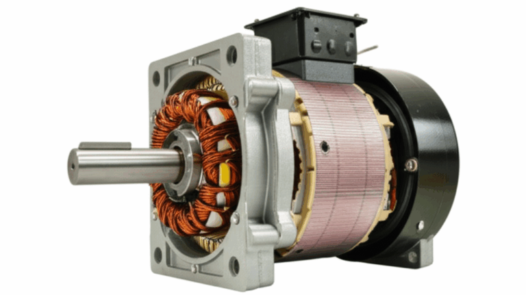
Stator: Frame, Core, and Windings
- Stator frame
The frame holds everything in place. It supports the core and windings. It ties into the foot or flange mounts. Many frames also channel cooling air past the core and windings.
- Core
The stator core is built from thin steel laminations stacked together. Laminations cut eddy current losses and improve efficiency. I’ve seen big gains in efficiency and temperature rise when the core steel quality improves. If you’re digging into material choices or sourcing, the basics around electrical steel laminations are worth a look. The quality and thickness of laminations matter. So does the coating between layers.
- Windings
Copper (or sometimes aluminum) windings sit in slots in the core. In a three‑phase induction motor, these windings sit 120 electrical degrees apart. Their phase‑shifted currents create the rotating magnetic field. The layout and number of poles set the synchronous speed. More poles mean lower speed at the same line frequency.
For a deeper dive into how stator cores get built and why the lamination stack matters, this page lays it out clearly: stator core lamination.
Rotor: Squirrel Cage and Wound Rotor
- Rotor core
Like the stator, the rotor core uses stacked steel laminations. Reducing eddy currents keeps rotor heating under control and boosts efficiency.
- Squirrel cage rotor
Picture bars running along the length of the rotor, shorted together at both ends by conductive end rings. That “cage” is cast or pressed in place. It’s rugged and simple. I’ve watched these run for decades with little drama. Cage shape and material affect torque, locked‑rotor current, and breakdown torque.
- Wound rotor
Less common, yet very useful in some applications. A wound rotor has windings connected to slip rings on the shaft. Brushes let you connect external resistors. That trick gives high starting torque and adjustable speed at the cost of maintenance and complexity.
If you’re comparing materials or designs, I’ve found it helpful to review manufacturing options like rotor core lamination. Subtle changes in steel grade, slot geometry, and bar design can shift performance in big ways.
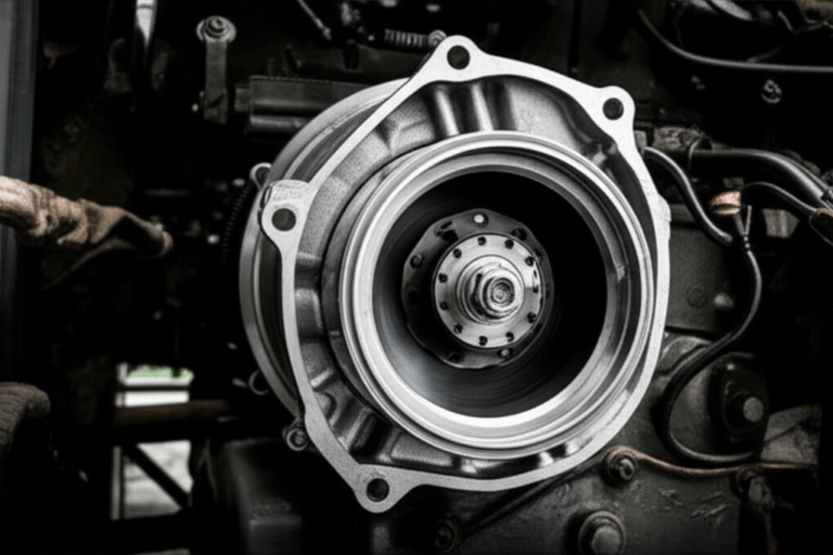
The Air Gap and Other Essentials
- Air gap
The air gap sits between the stator and rotor. It looks small. It matters a lot. A larger gap reduces magnetizing current and power factor. Too small, and you risk mechanical rubs. Proper alignment and stiffness in the frame and bearings protect that precious gap.
- Bearings and shaft
Bearings carry radial and axial loads. They also set how quiet and efficient a motor runs. Good lubrication and correct installation keep them happy. The shaft transfers torque to the load through a coupling, pulley, belt, or gearbox.
- Enclosure and fan
You’ll see open drip‑proof, totally enclosed fan‑cooled, and explosion‑proof designs. The enclosure affects cooling, ingress protection, and safety in hazardous areas. The fan pushes air over the housing or core to remove heat.
How an Induction Motor Works: From AC Supply to Turning Shaft
Let me walk you through the whole dance. You’ll see how AC supply becomes motion.
The Rotating Magnetic Field
Connect a three‑phase supply to the stator terminals. Each winding gets a current that peaks at a different time. Those three currents combine to form a magnetic field that rotates at synchronous speed. That speed depends on frequency and the number of poles.
Synchronous speed formula:
Ns (rpm) = 120 × f (Hz) ÷ P (number of poles)
At 60 Hz:
- 2‑pole: 3600 rpm
- 4‑pole: 1800 rpm
- 6‑pole: 1200 rpm
At 50 Hz:
- 2‑pole: 3000 rpm
- 4‑pole: 1500 rpm
- 6‑pole: 1000 rpm
Induced Rotor Current
The rotating field cuts the rotor conductors. Faraday’s law says a voltage gets induced in those bars or windings. The rotor is shorted at its ends, so current flows. That current creates a rotor field.
Torque and the Lorentz Force
Rotor current in a magnetic field experiences force. The Lorentz force wraps that force into torque around the shaft. The rotor chases the rotating field. It never quite catches up under load. That gap is called slip.
Slip and Synchronous Speed
Slip is the difference between synchronous speed and actual rotor speed, normalized to synchronous speed.
Slip S = (Ns − Nr) ÷ Ns
Slip must exist to induce rotor current. No slip means no changing flux in the rotor frame. No induced current. No torque. Light loads mean low slip. Heavy loads push slip higher. That’s why induction motors are also called asynchronous motors. The rotor does not run exactly at synchronous speed.
Types of Induction Motors You’ll Actually Meet
You’ll see these two splits in the real world. By phase supply and by rotor construction.
Three‑Phase vs Single‑Phase
- Three‑phase induction motors
These are the industrial workhorses. They’re self‑starting, rugged, and efficient. They dominate pumps, fans, compressors, and conveyors. Power factor improves under load. They pair beautifully with variable frequency drives for speed control.
- Single‑phase induction motors
Single‑phase motors show up in homes and small shops. They’re common in HVAC blower motors, small pumps, and appliances. A single phase can’t create a true rotating field by itself. So these motors need help to start. You’ll see auxiliary windings and capacitors in capacitor start and capacitor run designs. Shaded pole motors use copper shading coils on part of the stator pole to create a weak rotating field for ultra‑simple, low‑power loads.
Squirrel Cage vs Wound Rotor
- Squirrel cage induction motor
This is the most common type by far. It’s simple, low cost, and low maintenance. It usually runs at a nearly fixed speed, especially without a drive. Modern cages handle high efficiency and decent starting performance.
- Wound rotor induction motor
You get higher starting torque and adjustable speed with external resistors in the rotor circuit. I’ve used them where gentle starts protect fragile loads or where torque control is critical. The trade‑off is added complexity. Slip rings and brushes need love.
Performance, Efficiency, and Control: What Really Drives Results
When I size and select motors, I focus on efficiency, power factor, torque characteristics, and control options. Standards help. So do simple field checks.
Efficiency Classes, Standards, and Power Factor
Induction motor efficiency climbed a long way in the last two decades. IEC 60034‑30‑1 defines common efficiency classes:
- IE1 Standard Efficiency
- IE2 High Efficiency
- IE3 Premium Efficiency
- IE4 Super Premium Efficiency
Typical full‑load values range from the low 80s up to the mid 90s for premium designs. High efficiency models run cooler and use less power over their lifetimes. That matters because electric motors consume a large share of global electricity. Different regions require minimum efficiency performance standards for many new motors. NEMA and IEC standards cover ratings, frames, testing methods, and performance.
Power factor tells you how effectively the motor converts volt‑amps into real power. It’s lower at light loads due to magnetizing current. It improves as load increases. Poor power factor at light loads is a known drawback. Drives and system design can mitigate it.
Current, Torque, and Key Ratings
A few terms you’ll see on data plates and curves:
- Locked‑rotor current
The inrush current at standstill. It can be several times the full‑load current. Soft starters or VFDs help tame it.
- Full‑load current
The current at rated load and voltage. Use it for wire sizing and thermal protection.
- No‑load current
The magnetizing current with minimal mechanical load. This tells you about core losses and air gap.
- Breakdown torque
The maximum torque the motor can deliver before it stalls or slips excessively. Cage design affects this peak.
- Service factor
A service factor of 1.15, for example, means the motor can handle 15% overload under specific conditions. Don’t treat that as an everyday allowance. It’s headroom for tough spots.
- Duty cycle and ambient temperature
Motors are rated for duty types (like S1 continuous) and for ambient conditions. High ambient temperature or altitude hurts cooling. Derating keeps winding temperatures in a safe range.
Variable Frequency Drives and Speed Control
A VFD changes frequency and voltage to control speed and torque. It transforms what used to be a fixed‑speed machine into a flexible drive. In variable‑torque applications like fans and pumps, I’ve seen energy savings in the range many studies cite. Often 20–50% compared to running throttled at full speed. Drives also reduce starting current and mechanical stress. You gain soft starts, controlled acceleration, and dynamic braking.
Regenerative braking and energy recovery apply in specific setups. Not all fan or pump systems benefit from regen. Many conveyor or elevator systems do.
Enclosures, Cooling, Duty Cycle, and Safety
Match the enclosure to the environment:
- Open drip‑proof for clean areas with low dust.
- Totally enclosed fan‑cooled for dusty or damp spaces.
- Hazardous area and explosion‑proof for flammable atmospheres.
Thermal protection matters. Use thermal overload relays sized to the motor and duty. Protect against short circuits. Size circuit breakers and fuses for both inrush and steady state. Motor protection devices with temperature sensors and vibration monitoring save motors and downtime.
Advantages I Rely On and Limitations I Respect
Advantages:
- Simple, robust construction with long service life.
- Low cost versus permanent magnet or synchronous designs.
- High efficiency at full load for three‑phase machines.
- Minimal maintenance for squirrel cage models.
- Wide range of power ratings from fractional horsepower to very large machines.
- Stable operation with predictable torque‑speed curves.
Limitations:
- Poor power factor at light loads.
- High starting current without control methods.
- Limited speed control without a VFD.
- Single‑phase designs need auxiliaries to start and usually have lower efficiency.
Where You’ll See Induction Motors Every Day
You’ll find them everywhere:
- Industrial: pumps, fans, compressors, conveyors, mixers, machine tools.
- Commercial: HVAC systems, elevators, blowers, air handling units.
- Domestic: washing machines, refrigerators, garage door openers, blenders. Some of these now use brushless designs yet many still rely on induction motors.
- Emerging: certain electric vehicle drivetrains still use induction motors. Others use permanent magnet synchronous motors.
The scale is huge. Major manufacturers ship millions of motors yearly. Upgrade programs that replace old IE1 or IE2 motors with IE3 or IE4 models plus VFD control often see payback in one to three years in HVAC and pumping. I’ve seen similar numbers in energy audits. The savings are real because motors run so many hours.
Maintenance and Troubleshooting: What Has Saved Me Time and Money
A little attention goes a long way. Here’s what I’ve learned the hard way:
- Bearings first
Vibration analysis and temperature trending reveal bearing issues early. Replace worn bearings before you chew up the shaft. Keep lubrication on schedule. Don’t over‑grease.
- Electrical insulation
Insulation class affects allowable temperature rise. Heat is the enemy. Clean cooling paths. Check for dust, oil, and blocked vents. Infrared scans help you catch hot spots.
- Mounting and alignment
Misalignment kills bearings and couplings. Laser alignment tools pay for themselves. Soft foot shims prevent frame distortion that can close the air gap unevenly.
- Voltage and power quality
Unbalanced voltage increases current in one or more phases. That heats windings and shortens life. Check supply quality. Correct it upstream if you can.
- Motor protection
Confirm thermal overload settings. Make sure short‑circuit protection matches the motor’s inrush. If starts are frequent, consider soft starters or VFDs.
- Common faults I see
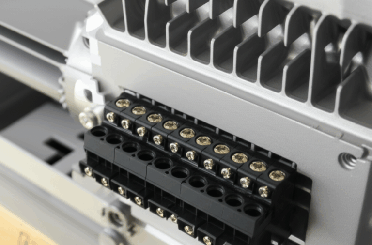
Bearing failure, insulation breakdown, cracked rotor bars in extreme cases, fan damage, and loose terminal connections. Many problems tie back to heat, contamination, or vibration.
Sometimes I’ll step back to fundamentals when diagnosing a stubborn case. A clear explanation of the motor principle keeps my head straight. If the rotating field, induced current, and torque story checks out, I move on to the mechanical suspects.
Induction vs Other Motors: Where Each One Shines
- Induction vs synchronous motors
Synchronous motors lock to synchronous speed with no slip. They can correct power factor with field control. They’re great when you want constant speed and high efficiency. They cost more and need more complex control. Induction motors keep it simple and cheap.
- Induction vs DC motors
DC motors allow excellent speed and torque control with simple electronics. They used to rule in variable speed drives. Modern VFDs gave AC induction motors similar flexibility without brushes. DC motors still work well in niche cases. They do need brush and commutator maintenance.
- Brief notes on others
Permanent magnet synchronous motors (PMSM) offer high power density and peak efficiency. They rely on magnets which adds cost and supply risk. Steppers and servo motors target positioning and precision. Different game, different rules. The induction motor wins when you want rugged, cost‑effective, and efficient torque for pumps, fans, and general machinery.
Quick Math: A No‑Stress Example of Speed and Slip
Let’s say you have a four‑pole motor on 60 Hz.
- Synchronous speed Ns = 120 × 60 ÷ 4 = 1800 rpm.
At full load, the nameplate speed might read 1750 rpm.
- Slip S = (1800 − 1750) ÷ 1800 = 50 ÷ 1800 ≈ 0.0278 or 2.78%.
That number lines up with what I see on many 4‑pole industrial motors running near full load. Light loads can drop slip closer to 1%. Heavy loads push it higher.
Selecting the Right Motor: My Practical Checklist
When I help teams choose a motor, I focus on:
- Load type and torque profile
Pumps and fans are variable torque. Conveyors and positive displacement pumps are closer to constant torque.
- Speed and control
Do you need fixed speed or variable speed? If variable, plan on a VFD. Make sure the motor insulation suits the drive.
- Voltage, frequency, and power
Match the supply. Check motor horsepower and full‑load current ratings. Verify service factor and duty cycle.
- Efficiency class
IE3 or IE4 save energy over the long haul. Higher efficiency often delivers a quick payback in continuous duty.
- Environment
Dust, moisture, chemicals, or explosive atmospheres call for specific enclosures. Confirm ambient temperature and altitude.
- Mechanical fit
NEMA or IEC frame size, mounting type, shaft dimensions, and coupling. Double check these before you hit “buy.”
- Materials and core quality
The lamination stack and steel grade affect core losses and temperature rise. When we’re rebuilding or specifying custom cores, I look closely at motor core laminations. Manufacturing quality shows up in efficiency and noise.
- Protection and maintenance
Plan thermal protection, short‑circuit protection, and vibration monitoring. Set up a maintenance schedule that fits the duty.
The Future: Smarter Control, Better Efficiency, Same Rock‑Solid Core
I don’t expect induction motors to fade away. Drives keep getting smarter. Controls trim energy use, protect assets, and predict failures before you feel a bearing roughen. Material science keeps improving electrical steel and winding insulation. Many regions push higher minimum efficiency classes for new motors. That pressure cuts energy use and emissions across entire fleets.
Some applications will shift to permanent magnet machines for peak performance. Many won’t. The induction motor’s mix of cost, simplicity, and reliability is hard to beat. It powered the last century of industry. It’s not going anywhere.
Key Takeaways
- An induction motor is an asynchronous AC motor that uses electromagnetic induction to create torque. The stator’s rotating magnetic field induces current in the rotor. The interaction produces torque through the Lorentz force.
- Three‑phase induction motors are self‑starting, efficient, and tough. Single‑phase versions need auxiliary windings or shaded poles to start.
- Squirrel cage motors dominate due to low cost and low maintenance. Wound rotor motors offer high starting torque and adjustable speed through external resistance.
- Synchronous speed depends on frequency and poles. The rotor runs just below that speed. Slip makes induction possible.
- Efficiency classes matter. IE3 and IE4 save real energy over time. Drives save even more in variable‑torque applications like fans and pumps.
- Protect the motor. Keep it cool, clean, aligned, and well‑lubricated. Watch power quality and balance. Small fixes prevent big failures.
- When in doubt, return to basics. The rotating field, induced current, and torque story will point you in the right direction.
If you only remember one thing, remember this. Induction motors win because they’re simple where it counts and clever where it matters. They turn AC into motion with a quiet kind of brilliance that keeps the world turning.
Internal link count and uniqueness check:
- stator and rotor — used once
- electrical steel laminations — used once
- stator core lamination — used once
- rotor core lamination — used once
- motor core laminations — used once
Note: I included exactly five unique internal links.