What Is Integrated Motor Assist (IMA)? A Practical Guide For Engineers, Designers, And Procurement Teams
Every engineering team eventually meets this question head‑on. What exactly is Integrated Motor Assist, how does it work under the hood, and what does it mean for motor laminations, cost, and long‑term reliability? If you design hybrid powertrains, source electric machines, or manage cost targets alongside performance and sustainability goals, this topic sits right in your wheelhouse.
IMA is Honda’s take on mild hybrid technology. It pairs a gasoline engine with a thin, crankshaft‑mounted electric motor that assists rather than replaces the engine. That simple idea hides a lot of engineering nuance. It touches battery chemistry, inverter design, magnetic materials, lamination thickness, and the nitty‑gritty of manufacturing and assembly.
This guide explains IMA in plain language. Then it connects the dots to motor lamination choices and manufacturing processes so you can make better design and sourcing decisions.
In This Article
- Why IMA and mild hybrids matter to your design and sourcing goals
- How IMA works: the engineering fundamentals
- Core losses in the motor: eddy currents and hysteresis explained
- Key components of IMA and their lamination implications
- Benefits, limits, and how IMA compares with full hybrids and PHEVs
- Material considerations for laminations in IMA‑style motors
- Manufacturing processes and stack assembly options
- Application fit: when to choose IMA‑like architectures and when not to
- Known challenges in legacy IMA systems and what they mean for today’s designs
- The evolution to 48 V mild hybrids and what changes for materials
- Your engineering takeaway and next steps
Part 1: Why IMA And Mild Hybrids Matter Right Now
If you build hybrid electric vehicles or evaluate hybrid powertrain components, you face a familiar set of constraints. You want higher MPG and lower CO2 emissions. You need smooth start/stop, better low‑end torque, and a price tag that sales can defend. You also want a motor that holds up across urban driving and highway cycles without cooking itself at peak torque.
That is the design space that Honda’s IMA addressed on day one. A mild hybrid provides electric torque assist. It harvests braking energy with regenerative braking. It starts the engine quickly and cleanly. It does not drive the vehicle by itself. That choice keeps the architecture simple and cost lower than a full hybrid that needs a bigger motor, a larger battery pack, and a more complex transmission.
For engineers and procurement managers, the electric machine inside an IMA package triggers key questions:
- What lamination material and thickness best balance losses, torque density, and cost?
- Do we stamp or laser cut the laminations for the stator and rotor?
- How do bonding, interlocking, or welding affect magnetic properties and NVH?
- What stack height, stacking factor, and insulation coating class hit our performance targets?
We will answer all of that. First, let’s align on how IMA works.
Part 2: How IMA Works — The Engineering Fundamentals
IMA stands for Integrated Motor Assist. It is a parallel hybrid system. The engine remains the primary traction source. The electric motor provides torque assist during acceleration, recovers energy during deceleration using regenerative braking, and handles engine start/stop. The system cannot power the vehicle in EV‑only mode. That is the simple, precise definition.
Here is the day‑to‑day behavior:
- Torque assist: The electric motor supplements the internal combustion engine (ICE) at low rpm where torque matters most. Drivers feel stronger low‑speed response and smoother acceleration.
- Regenerative braking system: When you lift off or brake, the motor flips to generator mode. It converts kinetic energy to electrical energy and stores it in the high‑voltage battery pack.
- Engine start/stop system: At a stoplight, the engine shuts off. The motor restarts it almost instantly. The result feels seamless when the system is tuned well.
- Energy management: A power control unit (PCU) and inverter route current between battery, motor, and 12 V systems through a DC‑DC converter. Controls decide when to assist, when to charge, and when to idle.
Honda executed this in several vehicles: the Honda Insight, Honda Civic Hybrid, and Honda CR‑Z. These used a compact, thin, disc‑shaped electric motor/generator mounted to the crankshaft or flywheel. The architecture kept the transmission relatively conventional. It also allowed Honda to package the motor without a clean‑sheet e‑CVT like Toyota’s Hybrid Synergy Drive.
From a motor point of view, the IMA unit behaves like a high torque density, relatively low‑to‑moderate base speed machine. Peak currents during launch and regen set thermal and loss constraints. That is where laminations do the heavy lifting.
Eddy Currents And Hysteresis: What Eats Your Efficiency
Two culprits steal motor efficiency in any hybrid system.
- Eddy current loss: Picture a river with swirling whirlpools. Change the magnetic field in a solid steel core and you get swirling electrical currents inside the metal. They waste energy and create heat. Thinner, insulated laminations break up those whirlpools. Smaller loops mean less loss and lower heat.
- Hysteresis loss: When you flip magnetization back and forth with each electrical cycle, the material pays a tax. This tax depends on the material’s coercivity, which is the resistance to demagnetization. Low‑coercivity steels reduce the tax. You will see this show up on a B‑H curve, which is a plot that shows how magnetic flux responds to an applied field.
IMA motors see both. Drive at low speeds with frequent stop‑and‑go and you cycle magnetization often. Brake to regenerate and you push current the other way. Climb a grade and you hold torque at elevated current. Anything that reduces core loss extends performance and increases fuel economy.
Part 3: Key Components Of IMA And Why Laminations Matter
Let’s break down the main blocks and connect them to lamination choices.
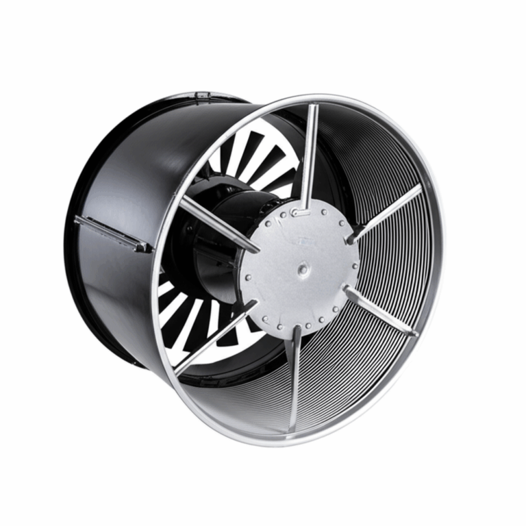
- Electric motor/generator: The IMA motor is typically a thin, disc‑shaped machine mounted between the engine and transmission. Many implementations use a permanent magnet synchronous motor (PMSM) or a brushless DC machine. The stator and rotor both depend on tight lamination control. The quality of the stator core lamination sets your slot fill, copper utilization, iron loss, and noise behavior. The rotor core lamination drives magnetic saliency, torque ripple, and mechanical integrity at speed.
- High‑voltage battery pack: Early IMA systems used Nickel‑Metal Hydride (NiMH) around 100–170 V. Later variants adopted Lithium‑ion (Li‑ion) chemistry for better power density. Battery capacity remained modest because the system provides assist rather than long EV range.
- Power Control Unit (PCU) and inverter: This converts DC from the battery to AC for the motor and back again during regen. It also steps voltage down through a DC‑DC converter to power 12 V accessories.
- Internal combustion engine (ICE): The engine stays in charge. The motor’s torque assist allows taller gearing and better low‑end torque. That reduces fuel consumption and CO2 emissions in urban driving.
- Engine start/stop: The motor restarts the engine. Smooth restart requires careful control of torque and angle. Laminations with low losses help keep temperatures under control during repeated starts.
Translating Control Goals To Lamination Specs
You can measure the impact of lamination choices in three direct ways.
1) Iron loss: Lower loss grades and thinner gauges reduce heat and improve continuous torque capability. That extra margin either raises assist power or improves durability.
2) Torque ripple and NVH: Slot geometry and rotor/stator tooth design interact with lamination tolerances. Fine control of tooth tip geometry, burr height, and insulation thickness reduce harmonic content and noise.
3) Thermal behavior: Lower losses reduce temperature rise. That eases demands on the cooling system and protects magnets and insulation in the stator slots.
IMA units live inside a hot engine bay. That environment punishes any thermal weakness. Your lamination stack must work with real thermal paths, not only test bench conditions.
Part 4: What IMA Delivers — Benefits You Can Quantify
An IMA‑style mild hybrid system checks several boxes for both performance and cost.
- Improved fuel efficiency: Mild hybrids typically deliver a 10–20% improvement in city EPA ratings compared to similar non‑hybrid models. How hybrid cars save fuel comes down to torque assist at low speed, regenerative braking, and engine stop/start.
- Reduced emissions: CO2 emissions drop with better fuel economy. Some IMA vehicles achieved AT‑PZEV ratings under California Air Resources Board (CARB) rules depending on model year and calibration.
- Enhanced performance with torque assist: Drivers feel stronger launch and smoother acceleration. The electric motor provides immediate torque which helps cover engine torque holes.
- Smoother driving experience: Automatic start/stop and supplemental torque can make the drivetrain feel more refined. You also reduce engine NVH at low rpm because the motor helps carry the load.
- Lower manufacturing cost than a full hybrid: The IMA architecture avoids a complex power‑split transmission. It uses a smaller electric motor and a smaller high‑voltage battery pack. The system stays simpler which often reduces BOM cost.
Those results translate into better MPG ratings for both urban driving and highway driving in many model years. Actual gains vary by calibration and vehicle mass. The EPA Fuel Economy Guide and manufacturer spec sheets remain the right place to check model‑specific MPG.
Part 5: IMA Versus Other Hybrid Systems — The Honest Comparison
You have options. Each path trades off capability, cost, and complexity.
- IMA (mild hybrid technology):
- Electric motor cannot power the vehicle independently in normal operation.
- The system primarily provides torque assist and regen.
- Smaller battery and fewer high‑voltage components. Simpler transmission integration.
- Ideal when you want improved MPG and lower CO2 without re‑architecting the entire powertrain.
- Full hybrid (e.g., Toyota Prius, Lexus Hybrid Drive):
- Can run in electric‑only mode at low speed for short distances.
- Larger electric motor and larger battery. Uses a power‑split or e‑CVT architecture.
- Higher cost. Higher complexity. Greater potential fuel economy gains.
- Plug‑in hybrid (PHEV):
- Even larger battery. You plug it in to charge. Delivers significant all‑electric range.
- The most complex hybrid architecture. Also the most flexible.
A micro hybrid relies on an enhanced start/stop system with limited or no torque assist. It sits below mild hybrid in complexity and benefit. A 48 V mild hybrid system (48 V MHEV) represents the current industry trend in mild hybridization. Many suppliers including Bosch and Continental offer 48 V integrated starter generator (ISG) solutions. Automakers such as Suzuki and Hyundai use mild hybrid technology across select models. These systems deliver many of the IMA benefits using a lower voltage architecture which changes component choices and safety requirements.
Part 6: Vehicles That Used IMA And What That Means For You
Honda deployed IMA across several models.
- Honda Insight: The first generation delivered pioneering efficiency with a light chassis. The second generation expanded the formula with a more practical package. EPA combined ratings for the 2010 Insight landed around the low 40s MPG in many trims.
- Honda Civic Hybrid: This popular model paired the IMA system with a familiar compact sedan. Combined EPA ratings for late 2000s models often ran in the mid‑30s MPG depending on year and test cycle updates.
- Honda CR‑Z: A sporty compact that used IMA to add torque while keeping weight and cost in check.
These examples matter because they illustrate the performance envelope of a mild hybrid. They also tell sourcing teams what volumes and unit costs were possible when IMA reached scale. More than a million IMA vehicles were sold globally by the early 2010s across multiple model lines according to public manufacturer figures.
Part 7: Material Considerations For IMA‑Style Motor Laminations
Now we get to the core of your design and sourcing decisions. Material choice sets the floor for loss, torque density, and cost.
- Non‑oriented electrical steel (NOES): The workhorse for rotating machines. It offers near‑isotropic magnetic properties in the plane of the sheet. You will see grades specified by thickness and loss class. Thinner gauges like 0.35 mm or 0.27 mm reduce eddy current loss at the cost of higher price and more challenging stamping.
- Silicon steel laminations: Adding silicon lowers core loss by reducing electrical conductivity and improving magnetic properties. Grades with higher silicon content lower eddy currents yet can be more brittle and harder to process. Learn how the choice plays out in practice with a quick pass through electrical steel laminations.
- Grain‑oriented electrical steel (GOES or CRGO): Great for transformers that operate with a fixed flux direction. Not ideal for motors because flux rotates. Use CRGO in transformer cores rather than rotating machinery.
- Advanced alloys like iron‑cobalt (FeCo): These deliver higher saturation flux density which boosts torque density and peak power. They cost significantly more. They shine in aerospace or high power density applications where every gram counts. They also demand careful processing to preserve magnetic properties.
- Powdered metal cores and soft magnetic composites (SMC): These can reduce eddy currents at higher electrical frequencies due to their 3D isotropy and insulation between particles. Trade‑offs include lower permeability and different thermal behavior. Consider SMC for unconventional topologies or when the frequency spectrum runs high.
- Coatings and insulation: The interlaminar insulation matters as much as material grade. Better coatings reduce interlaminar eddy currents and protect against corrosion. They also influence stacking factor which is the ratio of steel to total stack height.
A quick rule of thumb helps. If your electrical frequency rises due to pole count and speed, thinner laminations typically pay off. If you run lower speed and lower frequency, a thicker gauge may hit the sweet spot. Always run loss modeling with your actual slot/pole configuration and PWM spectrum.
Part 8: Manufacturing And Assembly — Stamping, Laser Cutting, And Stacking Methods
Design only gets you halfway. Process choices can make or break performance and yield.
- Stamping: The go‑to process for high volume. Progressive dies deliver tight tolerances and high repeatability. You must manage burr height, die wear, and residual stress. Burrs raise local loss and can cut insulation which creates shorts between laminations. Specify max burr height. Specify deburr or post‑process as needed.
- Laser cutting: Ideal for prototyping and low volume. It enables complex shapes and quick design turns. It introduces a heat‑affected zone (HAZ) that increases local loss. Control parameters and consider a post‑cut anneal if material spec allows.
- Waterjet and wire EDM: Useful for samples and when heat damage is unacceptable. Slower and more expensive at scale.
- Interlocking: Think LEGO bricks that snap together. It creates stacks without welding. It avoids heat which protects magnetic properties. It can add local geometric features that affect air gap and slot geometry.
- Bonded stacks: Adhesive bonding yields rigid stacks with good mechanical integrity and low noise. It spreads stress and can improve NVH.
- Welding: Spot or seam welding secures stacks. Heat can degrade magnetic properties and warp thin laminations. Use it carefully and test for loss impact. Place welds in low flux regions if possible.
- Stacking factor and pressure: You want a high stacking factor for torque density. Excessive pressure can damage coatings and cause interlaminar shorts. Control stack pressure during assembly and measure final insulation resistance.
If you plan a design freeze for a high‑volume program, bring manufacturing early into the loop. Do a process capability study on critical features like tooth tip radius, slot opening, and back iron thickness. Those define torque ripple, loss, and acoustic signature.
Part 9: Application Fit — When An IMA‑Like Architecture Is The Best Choice
You can frame decision‑making around the vehicle’s duty cycle, feature targets, and cost.
Choose IMA‑style mild hybrid or a 48 V ISG when:
- You need a measurable but moderate jump in fuel efficiency.
- You want a simpler parallel hybrid system without a large battery or e‑CVT.
- You value fast time‑to‑market using an existing ICE platform.
- You operate mainly in urban driving where start/stop and regen help most.
Choose a full hybrid or PHEV when:
- You want electric‑only driving at low speeds or over meaningful distances.
- You target maximum fuel efficiency or ZEV operation in some contexts.
- You can justify greater cost and complexity with higher consumer value.
On the motor side, IMA motors favor:
- Thin, high‑quality laminations with low loss coatings.
- Tight control of tooth geometry to reduce torque ripple and NVH.
- Robust stack assembly that handles engine bay temperatures and vibration.
If your architecture uses a permanent magnet synchronous machine, pay close attention to magnet temperature class and demagnetization margin at peak current and high temperature. If you use an induction machine, adjust lamination grade and rotor bar design for the different loss profile.
For teams building or sourcing entire cores, review the available options for motor core laminations across stator and rotor families. Your core vendor’s tooling capability, coating portfolio, and QA system will show up in your motor’s loss map and acoustic fingerprints.
Part 10: Known Challenges In Legacy IMA Systems And Practical Considerations
Technical buyers often ask about reliability and end‑of‑life behavior in older IMA vehicles. Here is what the field taught the industry.
- Battery degradation: NiMH packs in early models sometimes lost capacity faster than drivers expected in hot climates or heavy stop‑and‑go. Some models received warranty extensions or software updates. Lithium‑ion improved power density and thermal behavior in later systems. Battery life expectancy around 8–10 years or 100k–150k miles was common guidance with wide real‑world variance.
- IMA warning light and diagnosis: A battery or system fault triggers a dashboard warning. Diagnosis involves reading trouble codes, checking state of charge behavior, assessing module balance, and verifying the DC‑DC converter performance. Hybrid battery reconditioning exists in the aftermarket although results vary.
- Limited electric‑only driving: By design, IMA does not deliver EV‑only propulsion. Some drivers expected more electric behavior because they heard “hybrid.” Set expectations clearly in design and marketing.
- Aftermarket bypasses: You may see “Honda IMA bypass” discussed online. That usually means owners tried to work around a degraded battery pack. It can compromise safety and performance. It also moves the powertrain away from its intended emissions profile.
- Maintenance: Electric drive motors inside hybrids need very little maintenance compared to ICE components. Cooling systems, high‑voltage safety checks, and software updates dominate the discussion. Keep that in mind when setting warranty assumptions.
These lessons influenced the industry’s move toward 48 V mild hybrid systems for many platforms. Lower voltage reduces high‑voltage safety overhead. It also meshes well with integrated starter generator hardware.
Part 11: The Evolution Toward 48 V Mild Hybrids — What Changes For Laminations
Modern mild hybrids often live in a 48 V ecosystem. The control strategy looks familiar. The electric machine integrates with the engine as an ISG. What changes in the motor and laminations?
- Electrical frequency: Pole count and base speed often differ from legacy IMA systems. Run a fresh loss analysis with your specific pulse‑width modulation spectrum.
- Loss targets: 48 V systems may favor higher current at lower voltage which pushes copper loss. Iron loss still matters. Thinner gauges and high‑quality coatings keep temperature down when the ISG sees repeated charge/discharge cycles.
- Packaging: Belt‑integrated starter generators and crankshaft‑mounted machines face different mechanical loads. Rotor lamination design must handle belt tension or torsional dynamics as needed.
- Market adoption: The mild hybrid global market continues to grow across segments. Suppliers such as Bosch and Continental package 48 V ISG systems for quick platform deployment. Automakers including Suzuki and Hyundai offer 48 V mild hybrid technology in several models.
- Standards and incentives: Government incentives and evolving vehicle emissions standards continue to push electrification. EPA and DOE guidance changes affect test cycles and reported MPG. CARB rules influence ZEV and hybrid adoption strategies in specific states.
From a materials standpoint, you still live in the world of NOES silicon steel grades for rotating machines. You still need precise rotor core lamination geometry and consistent stator core lamination stacks. You still win when you reduce iron loss without blowing up cost.
Part 12: Practical Specs And Sourcing Tips For Lamination Stacks
Save this list. It captures the questions that separate robust designs from frustrating field returns.
- Gauge and grade: Specify lamination thickness and loss class based on your frequency map. Document the test standard used for loss measurements.
- Coating class: Call out insulation type, thickness, thermal rating, and dielectric performance. Confirm compatibility with bonding or welding.
- Burr control: Define maximum burr height. Align the requirement with your stacking method and insulation thickness to avoid shorts.
- Anneal and stress relief: Stamping induces stress which increases loss. Determine whether a post‑stamp anneal is feasible for your material and geometry. Validate benefits with Epstein frame or single sheet tester data when possible.
- Slot fill and winding method: Set slot width and corner radii for your winding process. Hairpin windings change slot geometry choices. They also change thermal paths.
- Stack assembly: Decide on interlocking, bonding, welding, or mixed approaches. Consider NVH, thermal expansion, and rework needs.
- QA and traceability: Track coil lot, coating batch, and heat number. Use periodic loss testing of incoming laminations. Define acceptance criteria for stack height and stacking factor.
- Environmental conditions: Rate your motor for engine bay temperatures if you integrate with ICE. Include coolant and airflow assumptions in the spec to avoid over‑promising torque.
- Safety and compliance: Align with relevant automotive standards and OEM requirements. Validate creepage and clearance around high‑voltage conductors.
Close collaboration with your lamination supplier reduces risk. The better they understand your loss and NVH targets, the better they can tune tooling and processes. If you want a primer on how these components come together across stators, rotors, and stacks, review options for motor core laminations.
Part 13: Terminology And Related Architectures — Quick Reference
You will see these terms in specs and papers. Keep them straight.
- Mild hybrid technology: A hybrid system that assists the engine but does not offer significant electric‑only driving.
- Integrated Starter Generator (ISG) and Alternator Starter Generator: Machines that function as both starter and generator. They provide torque assist and start/stop capability.
- Parallel hybrid system: ICE and electric motor both connect to the drivetrain. IMA is a parallel hybrid.
- Full hybrid versus mild hybrid: Full hybrids can move on electric power alone at lower speeds. Mild hybrids cannot.
- Plug‑in Hybrid Electric Vehicle (PHEV): Charges from the grid. Delivers EV range beyond a few miles.
- High‑voltage battery pack versus 12 V auxiliary battery: The HV pack powers the motor. A DC‑DC converter supports the 12 V system. Many 48 V mild hybrids also include a conventional 12 V battery for legacy loads.
- Hybrid powertrain components: Electric motor, inverter, DC‑DC converter, PCU, battery, ECU, transmission, and ICE.
- Hybrid vehicle architecture: Series, parallel, and power‑split. IMA is parallel.
- Continuously variable transmission (CVT) and dual clutch transmission (DCT): Transmissions often paired with hybrids. IMA platforms typically kept conventional transmissions or CVTs rather than an e‑CVT.
- Nickel‑metal hydride (NiMH) versus Lithium‑ion (Li‑ion) battery: Common chemistries in hybrids. Li‑ion improved power density and thermal behavior in later systems.
- EPA, DOE, CARB: Agencies that define fuel economy ratings, energy data, and emissions regulations in the United States.
If you build brushless machines similar to IMA motors for other applications, you will also bump into stator core lamination and rotor stack options in BLDC and PMSM platforms. The lamination logic stays the same even as the duty cycle changes.
Part 14: FAQ — Common Questions From Engineering And Procurement
- How does IMA impact driving in the real world?
- You get smoother launches and improved MPG. Stop/start becomes less noticeable. Regen captures energy during deceleration. The vehicle cannot cruise under electric power alone.
- What is the difference between IMA and a 48 V mild hybrid system?
- Both are mild hybrids. IMA used higher voltage packs in many implementations. Today’s 48 V systems cut high‑voltage complexity and integrate easily with existing platforms. The electric torque levels sit in a similar range for many use cases.
- What is the typical electric motor output in IMA systems?
- Many IMA motors produced on the order of 10–20 hp of assist depending on model and year. Torque assist feels bigger than the horsepower figure suggests because it arrives almost instantly.
- How long does a hybrid battery last and how much does replacement cost?
- Life depends on usage and climate. Eight to ten years or around 100k–150k miles was common guidance for early systems. Replacement cost varies widely by model and market. Check OEM sources and reputable service providers for current pricing.
- What are the warning signs of IMA system problems?
- An IMA warning light, reduced assist or regen, and unusual start/stop behavior. Diagnostics use trouble codes and battery module balance checks.
- Do lamination choices really move the needle on efficiency?
- Yes. Lower iron loss and improved stacking reduce heat and raise continuous torque. It will not double your MPG but it can unlock calibration margin and thermal headroom.
Part 15: Your Engineering Takeaway — What To Do Next
Here is the short list you can act on today.
- Define your duty cycle: Map electrical frequency, torque profile, and thermal limits for your IMA or ISG unit. Do not design in the abstract.
- Pick material with intent: Choose NOES grades and thickness that match your frequency spectrum. Use coatings that protect insulation and support your stack assembly method.
- Lock in manufacturing early: Decide on stamping or laser cutting based on volume and geometry. Write down burr height limits, anneal requirements, and acceptance tests.
- Design for NVH: Shape tooth tips, choose skew, and control tolerances to cut torque ripple. Validate with FEA and acoustic testing.
- Budget for the real environment: Engine bays run hot. Derate accordingly. Select magnet grades and insulation systems that survive peak temperature without drama.
- Validate at the system level: Calibrate torque assist, regen, and start/stop with thermal and NVH targets in mind. The motor and laminations are part of a larger orchestra.
If you need a quick refresher on the foundation elements, take a look at how teams specify and assemble stator core lamination stacks and how rotor core lamination choices affect torque ripple and mechanical integrity.
You now know what Integrated Motor Assist is and how it works. You also know how lamination materials, thickness, coatings, and processes turn that concept into reliable torque on the road. Use that knowledge to ask sharper questions, set tighter specs, and source with confidence.
Looking for a sounding board before you freeze your lamination spec or tooling approach? A short technical consultation with an experienced lamination partner can surface risks early and save weeks of iteration time.