Why Brushless Motors Reign Supreme: Unpacking Their Unrivaled Advantages
If you are weighing brushless versus brushed for your next design or procurement decision you are asking the right question. Brushless DC (BLDC) motors have earned their reputation for efficiency, lifespan, precision control, and low maintenance. Yet the story does not start and end with the motor label. Performance hinges on the materials and processes inside the stator and rotor core laminations. That is where efficiency is won, heat is managed, torque is built, and noise is tamed.
In this guide we answer why brushless motors are better then connect those advantages to the engineering fundamentals of motor laminations, electrical steel selection, and stack manufacturing. You will learn what matters, why it matters, and how to apply it in real projects from drones and e-bikes to EV traction drives, HVAC blowers, power tools, robotics, medical devices, and industrial automation.
You do not need to be a motor-core specialist. We will keep the physics clear and the recommendations practical so you can make confident design and purchasing decisions.
In This Article
- The Real Question Engineers Ask: Is Brushless Better for My Use Case?
- Engineering Fundamentals: Why BLDC Motors Deliver Higher Efficiency and Control
- Core Losses Explained: Eddy Currents, Hysteresis, and Heat
- Material Choices for Laminations: Silicon Steel, Cobalt Alloys, Amorphous Metals, SMC
- Manufacturing and Assembly: Stamping, Laser Cutting, Bonding, Interlocks, Skew
- Which Application Is This For? Power Tools, EVs, Drones, HVAC, Robotics, Medical
- Brushless vs Brushed: A Quick Summary for Decisions and TCO
- Procurement and DFM Checklist: Specifications That Protect Performance
- Your Engineering Takeaway and Next Steps
The Real Question Engineers Ask: Is Brushless Better for My Use Case?
Problem
Every design engineer faces the same tension. You need high performance and tight control without runaway cost or complexity. You want a quiet motor that runs cool and lasts for years. Procurement wants lower total cost of ownership and fewer maintenance headaches. End users want longer runtime, better torque, and predictable behavior under load.
Brushless motors promise all of that. Are they inherently better? Yes in most modern applications. However the degree of “better” depends on your lamination choices, winding strategy, rotor topology, and control electronics. The trade space includes:
- Efficiency versus cost
- Torque density versus thermal constraints
- Noise and vibration versus manufacturability
- Speed range and precision control versus complexity of the electronic speed controller (ESC)
- Material availability and vendor capability
Let’s break down the “why” behind brushless superiority first. Then we will map those advantages to the specific lamination materials and processes that unlock them.
Engineering Fundamentals: Why BLDC Motors Deliver Higher Efficiency and Control
Explain
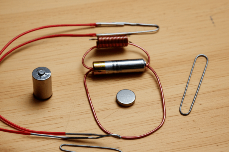
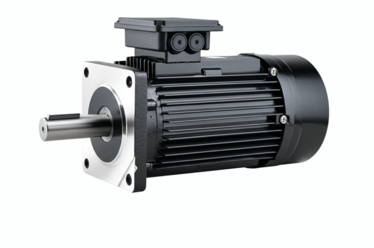
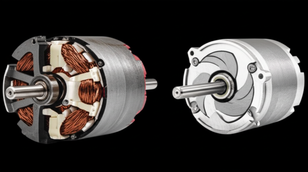
What makes a motor “brushless”? In a brushed DC motor the commutator and carbon brushes switch current mechanically. Friction, arcing, and wear are baked in. A BLDC motor removes those parts entirely. The electronics do the commutation. The rotor carries permanent magnets. The stator holds copper windings and stays fixed to the frame for easy cooling.
- Electronic commutation: An ESC sequences current into the stator phases based on rotor position. It may use Hall effect sensors or run sensorless by tracking back EMF. Sensorless control saves parts and cost. Sensored control gives better low-speed behavior and startup torque.
- Precise torque and speed control: The ESC drives waveforms that can be trapezoidal or sinusoidal. Field-oriented control (FOC) delivers smooth torque, low acoustic noise, and high efficiency across the RPM range. You get precise speed control under varying load.
- Power-to-weight gains: Permanent magnets in the rotor increase torque density. More torque per kilogram usually means smaller motors or more headroom for cooling. That is why drones, RC cars, and e-bikes lean so hard into BLDC.
- Fewer sparks and less EMI: No brush arcing means less electromagnetic interference. Sensitive environments like medical equipment or clean rooms benefit. Explosion-prone zones benefit because you eliminate a common source of ignition.
Important entities keep showing up in BLDC discussions:
- Stator and rotor
- Permanent magnets
- Hall sensors and ESCs
- Torque, RPM, efficiency, and thermal management
- Cogging torque and vibration
- Outrunner vs inrunner configurations
Outrunner motors place the magnets on the outer shell. The shell spins around a stationary stator. This geometry can deliver very high torque at modest diameter which suits drones and gimbals. Inrunner motors keep magnets inside a rotating inner cylinder. Designers pick inrunners for high-speed applications and compact packaging.
So why do brushless motors run cooler and quieter? You remove brush friction and commutator arcing. You move the copper to the stationary stator which makes heat easier to pull out. You drive the fields with clean electronics instead of mechanical contact. Better thermal management and less parasitic loss show up as longer battery life, less noise, higher reliability, and a higher ceiling for continuous torque.
Core Losses Explained: Eddy Currents, Hysteresis, and Heat
Now we get to the heart of motor laminations. The stator and rotor core funnel magnetic flux through the copper and magnets. Bad cores waste energy as heat. Good cores convert more electric power to mechanical work and keep the temperature in check.
Two primary core losses dominate:
- Eddy current loss: Think of eddy currents like tiny whirlpools in a river. The changing magnetic field induces circulating currents inside the steel. Those currents heat the metal and waste energy. Thinner laminations with insulating coatings break up the whirlpools. Less loop area means less eddy loss, especially at higher frequencies.
- Hysteresis loss: Magnetic domains do not flip direction for free. Each cycle costs energy. That loss scales with frequency and with the material’s coercivity which is the resistance to being demagnetized. Materials with low coercivity and narrow B-H loops lose less.
Frequency matters. BLDC machines often operate with electrical frequencies that rise with RPM and pole count. Push RPM high and eddy currents rise. Use pulse-width modulation and high switching frequency for clean control and you raise the effective AC content in the core. That is why lamination thickness, insulation quality, and base steel grade have such a large impact on BLDC efficiency.
Thermal paths matter too. You cannot avoid some loss. You can route heat through the stator teeth and yoke then into the housing. The stator sits in direct contact with the frame so it cools more easily than a brushed rotor that hides the coils inside. Better cooling stabilizes resistance in copper windings which keeps I²R loss in check. Cooler steel reduces temperature-dependent losses. The result is smoother operation with lower risk of overheating or demagnetizing the rotor magnets.
Key variables that drive core loss and thermal behavior:
- Lamination thickness: Typical NOES thicknesses include 0.50 mm, 0.35 mm, 0.30 mm, 0.27 mm, and 0.20 mm. Thinner usually means lower eddy loss at a given frequency.
- Insulation coating type and quality: Inorganic or organic coatings increase interlaminar resistance so sheets do not short together. High coating integrity supports low loss and high reliability.
- Base material: Non-oriented electrical steel (NOES) versus cobalt-iron versus amorphous metals versus soft magnetic composites. Each has distinct permeability, saturation, and loss profiles.
- Flux density target: Running closer to saturation increases local heating and pushes hysteresis loss up. Smart designs avoid deep saturation except in brief peaks.
- Processing damage: Burrs, heat-affected zones, and interlaminar shorts from poor cutting or welding increase loss. Good processes lower that risk.
Standards to guide specifications and verification include IEC 60404 series for magnetic testing, NEMA MG 1 for motor performance and definitions, and IEC 60034 for rotating electrical machines. Ask vendors for core-loss data at your operating frequency and flux density. The data should align with recognized test methods.
Material Choices for Laminations: Silicon Steel, Cobalt Alloys, Amorphous Metals, SMC
Guide
Here is a balanced view of common lamination materials for BLDC stators and rotors. We will emphasize trade-offs rather than push a single answer.
Non-Oriented Silicon Steels (NOES, M-Grades)
Best for: General-purpose motors, HVAC blowers, pumps, appliances, power tools, many EV auxiliaries, and industrial automation.
- Pros: Widely available, solid cost-performance balance, good mechanical strength, stable coatings, familiar to most manufacturers. High energy efficiency and low heat generation at mainstream frequencies.
- Cons: Higher core loss than cobalt alloys at elevated flux densities or very high frequencies. Thickness limits may constrain top-end performance.
- Typical thickness: 0.50 mm down to 0.20 mm. Thinner gauges improve high-speed efficiency and reduce eddy currents at the cost of higher price and handling complexity.
- Grades: Often designated M19, M27, etc. Lower numbers usually indicate lower loss. Ask for grade-specific loss curves at your required frequency.
When in doubt start with high-quality NOES. Then tailor thickness and coating to the application’s frequency and thermal limits.
Cobalt-Iron Alloys (Co-Fe)
Best for: High-power-density aerospace motors, high-speed compressors, traction motors with aggressive torque density, surgical tools, and applications that push toward high flux density and frequency.
- Pros: Very high saturation flux density which raises torque density. Lower core loss at high flux. Strong mechanical properties at elevated temperatures.
- Cons: Expensive. More challenging to machine or stamp cleanly. Can require specialized coatings and anneals. Not always necessary for cost-sensitive designs.
- When to choose: You need smaller size for the same torque, or you run at very high frequency, or you face tight temperature limits and must maintain low hysteresis.
Amorphous Metals
Best for: High-frequency applications where eddy loss dominates and core geometry tolerates strip-wound construction.
- Pros: Very low core loss at high frequency due to lack of crystalline grain structure. Excellent for transformers and some axial-flux motors.
- Cons: Brittle. Limited shapes and stack assembly options. Higher cost. Tougher to integrate in standard radial-flux BLDCs unless the design is tailored.
- When to choose: Specialized high-frequency machines or transformers. For many radial-flux BLDC motors NOES or Co-Fe remains the practical path.
Soft Magnetic Composites (SMC)
Best for: 3D flux paths, complex shapes, and high-frequency operation with low eddy currents inside the material.
- Pros: Powder metal with insulating binder supports three-dimensional magnetic flux with low eddy currents. Intricate shapes reduce assembly steps. Good for slotless or coreless concepts.
- Cons: Lower permeability than laminated steels. Usually lower saturation which caps torque density. Mechanical properties can limit thin features.
- When to choose: You need 3D flux and simplified manufacturing. Think compact robotics or specialty stators with unconventional tooth shapes.
Rotor and Magnet Considerations
BLDC rotors can use surface-mounted permanent magnets (SPM) or interior permanent magnets (IPM). IPM rotors embed magnets in the rotor core. This improves field-weakening for high-speed operation and boosts saliency for torque control. SPM rotors are simpler and common in drones and power tools that want high torque per diameter and straightforward assembly.
Magnets:
- NdFeB (neodymium iron boron): High energy product for great torque density. Sensitive to heat. Grade selection and proper thermal design protect against demagnetization.
- SmCo (samarium cobalt): Lower energy density than NdFeB but better high-temperature performance and corrosion resistance. Costlier.
Rotor cores still benefit from low-loss laminations because armature reaction and PWM harmonics drive AC fields in the iron. Pay attention to bridge thickness near magnet pockets to manage mechanical stress at speed without forcing the flux through saturated choke points.
If you want deeper insight into motor core design and the role of steel grade and insulation coatings you can review these overviews of electrical steel laminations and general-purpose motor core laminations.
Manufacturing and Assembly: Stamping, Laser Cutting, Bonding, Interlocks, Skew
You can choose a great material and still lose performance in production. Edge damage, burrs, and interlaminar shorts drag efficiency down. Here is how common processes trade off.
Cutting Processes
- Progressive die stamping: Best for high volumes with tight repeatability and low piece cost. Pros include good burr control and consistent geometry once tools are dialed in. Cons include upfront tool cost and lead time. Careful tool design and maintenance keep burr height low which protects stacking factor and reduces interlaminar shorts.
- Laser cutting: Ideal for prototyping and low to medium volumes or complex shapes. Fast iterations with no die cost. Watch for heat-affected zones that can increase local losses. Proper parameters and post-process stress relief help.
- Wire EDM: High precision with minimal thermal damage. Slower and more expensive. Good for small runs, intricate bridge features, or tight tolerances near magnet pockets.
- Waterjet: No heat-affected zone but can leave surface roughness that affects coating integrity. Less common for production laminations.
Your selection should reflect lifecycle volume and geometry complexity. Laser and EDM get you to first spin fast. Stamping wins at scale for simpler outlines.
Stacking and Joining
Stacks need mechanical integrity, electrical isolation between laminations, and thermal paths that support heat flow out of the stator or rotor.
- Interlocking features: Tabs and notches snap like LEGO bricks to build stacks. Assembly is fast and cost effective. Interlocks preserve interlaminar insulation if kept shallow and well designed.
- Bonding/adhesive lamination: Thin adhesive layers between sheets increase mechanical rigidity, reduce vibration, and block interlaminar shorts. Bonding can lower noise and improve core loss compared to welding or heavy interlocks. It also improves smooth operation and vibration reduction in high-speed applications.
- Riveting and cleating: Simple and robust. Use sparingly to avoid shorting lamination layers. Nonconductive rivets help, yet they add steps.
- Welding: Strong and permanent. It risks localized shorting and heat damage. If you must weld, place short welds in low-flux regions and control heat input.
- Skewing: Skewing stator slots or rotor magnets reduces cogging torque and acoustic noise. You can skew via segmented laminations or by stacking each lamination with a small offset. This technique smooths torque ripple for precision control.
You can explore typical stator core stack construction here: stator core lamination. For rotor architectures and pocketing strategies, see rotor core lamination. If you are designing a BLDC machine specifically, these considerations roll up into your bldc stator core geometry and assembly plan.
Insulation Coatings and Stacking Factor
Coatings do more than stop shorts. They influence stacking factor which is the ratio of iron height to total stack height. Thicker coatings lower stacking factor. Too thin can raise risk of interlaminar conduction. Typical coatings include inorganic phosphate systems and hybrid organic-inorganic types rated for higher temperatures.
Specify:
- Coating class and thickness range
- Minimum interlaminar resistance
- Maximum burr height per edge
- Post-processing anneal requirements
- Allowed joining methods and weld energy limits if applicable
Winding Choices and Slot Geometry
Concentrated windings (often used in BLDC) reduce end-turn length which helps copper loss and compactness. Distributed windings can cut torque ripple and acoustic noise. Slot shape and tooth tip design influence cogging torque and harmonic content in the back EMF. Combine good slot geometry with ESC FOC for smooth and quiet operation.
Control Electronics and EMI
ESC design and PWM strategy steer acoustic and electrical behavior. Higher switching frequency can reduce torque ripple at the cost of increased switching loss and potential high-frequency core loss. Synchronous rectification and dead-time optimization raise efficiency. Layout, shielding, and proper grounding contain EMI. The intrinsic lack of brush arcing makes BLDC motors suitable for sensitive electronics and medical devices where electromagnetic interference must stay low.
Which Application Is This For? Power Tools, EVs, Drones, HVAC, Robotics, Medical
Guide
You do not pick a single “best” for all cases. You match material and process to the job.
Power Tools and Cordless Equipment
Why brushless wins: You get longer battery life, higher torque density, and superior thermal management. Users report extended run time per charge along with lower noise and fewer service events. Pro-grade brands like DeWalt, Makita, Milwaukee, and Bosch moved their flagship cordless lines to BLDC for that reason.
Material and process guidance:
- NOES around 0.35 mm down to 0.27 mm often meets the need. Thinner gauges help when you push RPM and high electrical frequency.
- Concentrated windings and outrunner or compact inrunner topologies are common.
- Interlocking stacks or bonded stacks both work. Bonding can lower NVH in premium models.
- Specify tight burr control and verify core loss at the intended frequency.
Electric Vehicles and E-Bikes
Why brushless wins: Efficiency and torque density determine range and packaging. Modern EVs use brushless AC machines such as permanent magnet synchronous motors or induction variants. E-bikes rely on BLDC for compact hub or mid-drive packages.
Material and process guidance:
- EV traction often leans toward high-grade NOES or Co-Fe when torque density must rise in tight envelopes. Use segmental stators to ease winding and assembly. Consider IPM rotors for field-weakening.
- E-bikes often succeed with high-quality NOES, 0.35 mm or thinner for high efficiency at typical cadence-derived frequencies.
- Robust bonding and precision stamping keep losses low and NVH in check.
- Verify thermal limits on magnets and use appropriate grades to guard against demagnetization.
Drones and RC Vehicles
Why brushless wins: High RPM, high thrust-to-weight, precise speed control. Outrunner BLDC motors dominate drones due to their power-to-weight ratio and ability to cool the stator effectively.
Material and process guidance:
- Thin NOES sheets such as 0.27 mm or 0.20 mm control eddy losses at very high electrical frequencies.
- Laser-cut or stamped laminations with excellent coating integrity prevent interlayer shorts.
- Skew may be limited by geometry. Focus on slot shape and ESC control to reduce cogging torque.
HVAC Systems and Appliances
Why brushless wins: Energy savings, quiet operation, and long life. BLDC furnace blowers, condenser fans, and washing machine drives save energy and deliver precise airflow or drum speed.
Material and process guidance:
- NOES with moderate thickness like 0.35 mm performs well at HVAC frequencies.
- Bonded stacks and balanced rotors reduce vibration and noise which directly improves user experience.
- Digital motor control and sensorless operation reduce parts and maintenance.
Industrial Robotics and Automation
Why brushless wins: Servo-class precision, low cogging torque, reliability in continuous duty, and minimal EMI. BLDC servo motors offer tight position control and smooth motion.
Material and process guidance:
- Choose low-loss NOES or Co-Fe depending on torque density and size constraints.
- Aggressive skewing and refined slot geometry reduce cogging. Bonded stacks help noise and vibration.
- Pair with FOC drives and high-resolution encoders or resolvers. Shield cabling to keep EMI low.
Medical Devices and Clean/Explosive Environments
Why brushless wins: No brush sparks reduces EMI and ignition risk. Quiet, smooth operation benefits surgical tools, dental drills, and pump systems.
Material and process guidance:
- Co-Fe or high-grade NOES for small, high-speed spindles that must stay cool.
- Wire EDM or precision stamping to protect magnetic properties near small features.
- Carefully specify coating class and bonding for sterile or clean-room compatible assemblies.
Marine and Aerospace
Why brushless wins: Reliability, efficiency, and weight reduction. Aerospace demands power-to-weight with robust thermal performance. Marine propulsion values quiet operation and durability in harsh environments.
Material and process guidance:
- Co-Fe for maximum saturation in tight envelopes. Advanced bonding for stability and vibration resistance.
- Surface treatments and coating systems that resist moisture and corrosion.
Brushless vs Brushed: A Quick Summary for Decisions and TCO
Engineers and procurement teams need the short version. Here it is.
- Efficiency: Brushless typically 85 to 90 percent or higher. Brushed often 75 to 80 percent. No brush friction or arcing means less waste and cooler running.
- Lifespan: BLDC often 10,000+ hours limited mostly by bearings and insulation. Brushed life is limited by brush and commutator wear.
- Maintenance: Brushless is nearly maintenance free. Brushed requires brush replacement and commutator cleaning with downtime.
- Heat and noise: BLDC runs cooler and quieter since the stator is easier to cool and there is no brush noise.
- Control precision: ESCs deliver precise RPM and torque control even under variable loads. Brushed control is simpler yet less precise.
- EMI: BLDC avoids brush arcing so emissions drop. This helps in sensitive electronics and medical settings.
- TCO: Initial cost can be higher due to the ESC and manufacturing. Over life the reduced energy consumption, longer service intervals, and reliability usually lower total cost of ownership.
- Safety: No sparking makes brushless friendlier in explosion-proof designs and clean rooms.
Want a practical angle on the magnetic core pieces behind those gains? Start with the structure and function of motor core laminations. It shows how stator and rotor stacks convert electrical energy to smooth mechanical work.
Procurement and DFM Checklist: Specifications That Protect Performance
Empower
Use this checklist to turn “brushless is better” into repeatable, audited results. It will also make your vendor conversations efficient.
Material requirements
- Base steel: Specify NOES grade or Co-Fe alloy with target core-loss limits at your operating frequency and flux density. Request data per IEC 60404.
- Thickness: Choose gauge aligned with your electrical frequency. Thinner laminations for higher RPM and PWM frequencies.
- Magnetics: Ask for guaranteed permeability range and saturation flux density. Verify batch-to-batch consistency.
Insulation and coatings
- Coating class and thermal rating appropriate for winding and operating temperature.
- Minimum interlaminar resistance values.
- Max allowable burr height per edge. Define measurement method and sample plan.
Manufacturing processes
- Cutting: Define acceptable processes for your phase of development. Laser or EDM for prototype. Progressive die for production. Specify post-processing anneal if needed to restore magnetic properties.
- Stacking: Approve interlocks, bonding, or rivets. If welding is allowed define weld locations, energy, and number of welds in low-flux zones.
- Skew: Define skew angle or segment plan to reduce cogging torque for precision applications.
Geometry and winding
- Slot shape and tooth tip design aimed at lower cogging and harmonic torque. Call out limits for slot opening and bridge features.
- Copper fill factor targets with winding method (concentrated or distributed).
- Tolerance stack-up that protects air-gap accuracy and rotor concentricity.
Rotor details
- Rotor lamination design with bridge thickness and pocket features that balance mechanical strength and magnetic performance.
- Magnet type, grade, and temperature rating with safety margin for demagnetization.
- Retention method (sleeve, potting, or banding) and overspeed test requirements.
Testing and documentation
- Core loss test at specified frequency and flux density with method per IEC 60404.
- Dimensional inspection with burr height metrics and stack factor.
- Electrical test for interlaminar shorts on sample stacks.
- Motor-level test: vibration, noise, and thermal rise curve under representative load.
- Standards alignment: NEMA MG 1 and IEC 60034 where applicable.
Supplier capabilities
- Sample-to-production plan with process controls to keep burrs, coating integrity, and stack quality consistent.
- Traceability and certification for materials. Quality system such as ISO 9001 helps.
- Application support for BLDC specifics like skewing, bonding, and magnet handling.
Your Engineering Takeaway and Next Steps
You asked why brushless motors are better. The short answer says they waste less energy, run cooler and quieter, deliver higher torque density, and need less maintenance. The complete answer says those gains ride on the back of smart lamination choices, robust manufacturing, and well tuned electronic control.
Key points to remember
- Brushless motors eliminate brush friction and arcing which boosts efficiency and reliability. The stator sits on the outside so you cool it better which stabilizes performance.
- Core losses set your efficiency ceiling. Thinner, well insulated laminations reduce eddy currents. Low-coercivity materials cut hysteresis loss.
- NOES works for most designs. Use cobalt-iron for extreme torque density or very high frequency. Consider amorphous or SMC only when their unique benefits outweigh handling and cost.
- Manufacturing choices matter. Stamping rules at volume. Laser and EDM shine in development and complex geometries. Bonded stacks and skew reduce vibration, cogging, and acoustic noise.
- Rotor topology drives behavior. IPM supports high-speed field-weakening and robust torque. SPM keeps designs simple and light.
- BLDC motors suit EVs, drones, HVAC, robotics, medical devices, and appliances because they pair efficiency with precision control and reliability. They also reduce EMI and simplify explosion-proof design.
Practical next steps
- Define your electrical frequency range from RPM and pole count. Select lamination thickness that keeps eddy currents in check at that frequency.
- Request core-loss curves from your material supplier at your operating B and Hz. Verify with IEC 60404 test methods.
- Lock in coating class and burr height limits. Put them in the drawing. They protect interlaminar resistance and stacking factor.
- Choose a stacking strategy. Interlocks for speed and cost. Bonding for low noise and high structural integrity.
- Review stator slot shape and skew needed to hit NVH and cogging targets. Validate with FEA then confirm with prototype testing.
- Partner early with a lamination supplier who can support both prototype and production. Align on stamping versus laser/EDM and on post-process anneals.
- Close the loop with an ESC that supports FOC when you need low ripple torque, quiet operation, and high efficiency.
If you are aligning a BLDC design with manufacturable lamination stacks and you want a concise overview of rotor and stator core options, these references can help:
- Overview of stator core lamination
- Overview of rotor core lamination
- Overview of electrical steel laminations
- Overview of bldc stator core
- Overview of motor core laminations
Final thought. Brushless motors do not just edge out brushed motors. They represent a leap. Energy goes into motion instead of heat. Bearings become the main wear item. Digital control lets you dial in RPM and torque with confidence. The right laminations turn those theoretical wins into everyday performance that your users can feel and your finance team can measure.
Notes and sources for further reading
- NEMA MG 1: Motors and Generators. Definitions and performance guidelines.
- IEC 60034: Rotating Electrical Machines. General requirements and test methods.
- IEC 60404 series: Magnetic materials. Methods for measuring core loss, permeability, and related properties.
- IEEE Transactions on Industry Applications and IEEE Transactions on Magnetics publish peer-reviewed studies on BLDC efficiency, materials, and control strategies.
Common keywords and entities covered in this guide include: brushless vs brushed motor comparison, BLDC motor benefits, efficiency of brushless motors, lifespan of brushless motors, maintenance-free motors, higher torque brushless motor, better speed control brushless, reduced noise brushless motors, cooler running motors, energy saving motor technology, power-to-weight ratio brushless, durability of BLDC motors, reliability of brushless tools, electronic commutation advantages, permanent magnet motors benefits, no friction in brushless motors, heat dissipation brushless, increased battery life power tools, cordless tool performance, electric vehicle motor choice, drone motor technology, RC car motor efficiency, industrial automation brushless motors, robotics motor advantages, appliances with brushless motors, HVAC system brushless benefits, medical device motors, lower operating costs motors, long term motor value, how brushless motors work, components of a BLDC motor, stator rotor configuration, Hall effect sensors motors, electronic speed controller, torque density brushless, RPM capabilities brushless, overheating prevention motors, sparking issue brushed motors, electromagnetic interference, cost-benefit brushless motors, future of electric motors, motor technology evolution, high performance motors, quiet motor operation, precision control motors, what makes a motor brushless, disadvantages of brushed motors, when to choose brushless, why professionals prefer brushless, brushless motor types, outrunner vs inrunner, cogging torque brushless, smooth operation motors, greater power output motors, compact motor design, high-speed applications, low-speed torque control, less wear and tear motors, optimized motor performance, advanced motor control, digital motor control, sensorless brushless motors, position sensing in BLDC, fewer moving parts motors, no mechanical commutator, elimination of carbon brushes, superior thermal management, vibration reduction motors, contamination resistance brushless, explosion-proof motor design, clean room applications, dental drill motors brushless, surgical tool motors, computer fan motors, washing machine motors, vacuum cleaner brushless, e-bike motor benefits, marine propulsion motors, aerospace motor technology, small form factor motors, high energy efficiency motors, extended run time tools, environmental benefits motors, reduced carbon footprint motors, sustainable motor solutions, modern motor design, advanced material motors, magnetic field control, software-driven motor control, next-gen motor technology, investment in brushless motors, understanding BLDC technology, benefits of permanent magnets in BLDC, how brushless motors generate less heat, impact of no brushes on motor life, why brushless motors are more efficient, comparing motor technologies, and future proof motor solutions.
This article aimed to answer the “why” and the “how” in one place so you can move ahead with a design that hits your targets on efficiency, durability, performance, and cost.