Why Eddy Currents Flow in Circles: Understanding the Fundamental Physics of Their Shape
As an engineer or designer, you’re constantly battling the laws of physics to squeeze out every last bit of efficiency from an electric motor or transformer. You know that core losses are a primary enemy, and that these losses are driven by invisible forces like hysteresis and, most notably, eddy currents. You’ve likely heard the solution a thousand times: use thin, insulated laminations. But have you ever stopped to ask a more fundamental question? Why are these pesky, heat-generating currents called “eddy” currents in the first place? Why do they flow in swirling, circular paths instead of straight lines?
Understanding this core principle isn’t just an academic exercise. It’s the key to truly grasping why laminations work, why material choice is so critical, and how you can make more informed decisions to optimize your design for performance, temperature, and cost. If you’ve ever wanted to look beyond the datasheets and understand the elegant physics governing motor efficiency, you’re in the right place.
What We’ll Cover
This guide will break down the fundamental principles behind the circular nature of eddy currents and connect them directly to practical engineering decisions. Here’s a roadmap of what we’ll explore:
- The Genesis of Eddy Currents: A Tale of Changing Fields
- The Shape-Maker: Why the Flow is Circular, Not Straight
- The Enforcer: How Lenz’s Law Dictates Direction and Creates Opposition
- From Physics to Practice: How Eddy Currents Impact Your Design
- Taming the Whirlpool: A Guide to Lamination Materials and Strategies
- Manufacturing Matters: Breaking Up the Current Paths
- Matching the Solution to Your Application
- Your Engineering Takeaway
The Genesis of Eddy Currents: A Tale of Changing Fields
Before we can understand the shape of eddy currents, we have to start at their source: electromagnetic induction. The entire phenomenon rests on a cornerstone of physics discovered by Michael Faraday in the 1830s.
Faraday’s Law of Induction is elegantly simple yet profound. It states that a changing magnetic field will induce an electromotive force (EMF), or voltage, in any closed electrical circuit it passes through. Think of EMF as the “pressure” that pushes electrons to move. Without this pressure, there’s no current.
The key word here is changing. A steady, constant magnetic field sitting next to a block of copper won’t do anything. But if that magnetic field starts getting stronger or weaker, or if you move the copper block through the field, the magnetic flux passing through the conductor changes. This change is the trigger. In a motor, this happens constantly as the alternating current (AC) in the windings creates a rapidly rotating and fluctuating magnetic field that sweeps through the stator and rotor cores.
This induced EMF is the birth of an eddy current. The conductor itself—be it an iron core, an aluminum plate, or a copper pipe—provides the “closed circuit” for the current to flow.
The Shape-Maker: Why the Flow is Circular, Not Straight
So, a changing magnetic field creates an electrical “push” (EMF). But why does this push result in a circular current? Why doesn’t it just push electrons in a straight line from one side of the conductor to the other?
The answer lies in the unique nature of the electric field created by a changing magnetic field. This is a crucial distinction.
This is the absolute heart of the matter. The very nature of the “push” is rotational. One of Maxwell’s Equations, which is the mathematical formulation of Faraday’s Law, quite literally describes this curling effect (Curl(E) = -dB/dt).
The Whirlpool Analogy
Imagine a large, still pond. If you push the water from one side, you create a simple, linear flow. This is like the electric field from a battery pushing current through a wire.
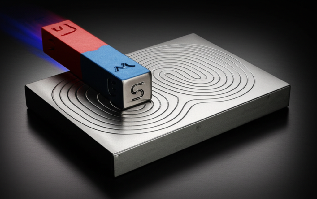
Now, imagine placing a large paddle in the center of the pond and rotating it. You aren’t pushing the water from the edge; you’re creating a rotational disturbance in the middle. What happens? The water around the paddle begins to swirl, forming a vortex or an “eddy.” The “push” you’re creating is inherently circular, and the water naturally follows that looping path.
This is exactly what happens inside a conductor. The changing magnetic field is the spinning paddle. It creates a swirling, looping electric field. The free electrons within the conductor are the water—they are compelled to follow these closed-loop paths, creating the circular flow we call an eddy current. The term “eddy,” borrowed from fluid dynamics, is a perfect description of this electrical whirlpool.
The Enforcer: How Lenz’s Law Dictates Direction and Creates Opposition
We’ve established that a changing magnetic field creates a circular electric field, which in turn drives a circular eddy current. But which way does it spin—clockwise or counter-clockwise? This is where another fundamental principle, Lenz’s Law, comes into play.
Lenz’s Law is a consequence of the conservation of energy and adds a crucial detail to Faraday’s Law. It states:
> The direction of the induced current is always such that its own magnetic field opposes the change in magnetic flux that produced it.
Let’s break that down with a simple example: dropping a strong magnet through a copper pipe.
This constant opposition is the source of many real-world effects. It’s the principle behind eddy current braking on roller coasters and high-speed trains. The circular currents create magnetic fields that act as a powerful, frictionless brake against the motion that created them. It’s also the source of magnetic damping in sensitive laboratory scales, where eddy currents quickly quell oscillations.
And, most relevant to motor design, this opposition is a source of energy loss. The energy to create these opposing magnetic fields and to push the electrons through the resistive material of the core has to come from somewhere. It comes directly from the motor’s power source, manifesting as unwanted heat.
From Physics to Practice: How Eddy Currents Impact Your Design
Understanding that eddy currents are circular whirlpools of energy loss is the first step. The next is quantifying them. The power dissipated as heat by eddy currents in a material can be approximated by the formula:
$P_{loss} \propto B^2 \cdot f^2 \cdot d^2 / \rho$
Let’s unpack this, because every term represents a critical lever you can pull as a designer:
- B (Magnetic Flux Density): A stronger magnetic field creates a more powerful “push,” resulting in stronger eddy currents. Power loss increases with the square of the flux density, so even a small increase in B has a big impact.
- f (Frequency): A faster rate of change (higher frequency of the AC) induces a stronger EMF. Again, the power loss increases with the square of the frequency. This is why eddy currents are a massive challenge in high-frequency applications like EV motors and modern power electronics.
- d (Thickness of the Conductor): This is the most important factor from a mechanical design perspective. A thicker conductor provides a wide, easy path for a large, powerful whirlpool to form. The power loss increases with the square of the thickness. Halving the thickness of the path reduces the eddy current loss by a factor of four! This is the entire reason we use laminations.
- ρ (Resistivity of the Material): Resistivity is a material’s inherent opposition to current flow. A higher resistivity makes it harder for electrons to move, thus weakening the eddy currents for a given EMF. This is why we add silicon to steel for motor cores—it significantly increases the material’s electrical resistivity.
By looking at this formula, the engineering solution becomes clear: to tame the eddy current whirlpool, you must break up its path. You do this by making ‘d’ (thickness) as small as practical and by choosing a material with a high ‘ρ’ (resistivity). This is precisely what a stack of insulated electrical steel laminations achieves.
Taming the Whirlpool: A Guide to Lamination Materials and Strategies
Because you can’t eliminate the changing magnetic field (you need it to make the motor work!), your primary strategy for controlling eddy currents is to disrupt their circular paths through intelligent material selection and mechanical design.
The solution is to build the motor core not from a solid block of iron, but from a stack of very thin sheets, or laminations. Each sheet is coated with a thin insulating layer (like a varnish or oxide). This forces the would-be giant whirlpool of current to break up into thousands of tiny, insignificant eddies, each confined to the thickness of a single lamination. The combined power loss of these tiny eddies is drastically lower than that of one large one.
Choosing the right material for these laminations is a critical balancing act between magnetic performance, electrical resistivity, and cost.
Silicon Steels (The Workhorse)
Also known as electrical steel, these are iron alloys specifically designed for electromagnetic applications. The addition of silicon (typically up to 6.5%) is a game-changer because it dramatically increases the material’s electrical resistivity (ρ) without severely harming its excellent magnetic properties (like high permeability). They are the go-to choice for the vast majority of motors, generators, and transformers. They are often categorized by “M-grades” (e.g., M-19, M-27) which denote their core loss characteristics.
- Pros: Excellent magnetic performance, relatively low cost, wide availability, well-understood properties.
- Cons: Core losses can become significant at very high frequencies (above a few hundred Hz).
Advanced Alloys (The Specialists)
For applications demanding the absolute highest performance, especially in high-frequency environments, engineers turn to more exotic materials.
- Cobalt-Iron Alloys: These materials offer extremely high magnetic saturation, meaning they can handle much higher magnetic flux densities (B) than silicon steels. This allows for smaller, more power-dense motors, making them ideal for aerospace applications where weight and size are critical. Their high performance comes at a significantly higher cost.
- Amorphous and Nanocrystalline Metals: These materials have a non-crystalline, glass-like atomic structure. This structure results in very high electrical resistivity and excellent high-frequency performance, drastically reducing eddy current losses. They are often used in high-frequency transformers and specialized motor designs.
Manufacturing Matters: Breaking Up the Current Paths
Simply choosing the right material isn’t enough; how you shape and assemble the motor core laminations is equally important for preserving its performance.
Stamping vs. Laser Cutting
- Stamping: This is the workhorse of high-volume production. A die is used to punch the lamination shape from a roll of electrical steel. It’s fast and cost-effective for large quantities. However, the stamping process can induce mechanical stress at the edges of the lamination, which can negatively affect the magnetic properties and increase losses. Post-stamping annealing (a heat treatment process) is often required to relieve this stress.
- Laser Cutting: This process uses a high-power laser to cut the lamination shape. It offers incredible precision and design flexibility, making it perfect for prototyping, complex geometries, and low-volume production. It induces very little mechanical stress but can create a small heat-affected zone at the edge. For high-volume runs, it is generally slower and more expensive than stamping.
The Critical Role of Insulation and Stacking
The thin insulating layer between each lamination is the hero of eddy current reduction. If this insulation is compromised, or if laminations become electrically shorted together, the benefits are lost. Burrs from the cutting process or excessive pressure during assembly can bridge the gap, allowing larger eddy currents to form and creating localized hot spots.
Common methods for stacking and securing laminations include:
- Welding: While a common method, welding can damage the insulation, short-circuit laminations near the weld bead, and introduce thermal stress. It must be done carefully and is often limited to specific points on the outer diameter.
- Interlocking: This mechanical method uses small stamped features that interlock or “stake” the laminations together, like LEGO® bricks. It avoids the thermal damage of welding and creates a rigid core.
- Bonding: Applying an adhesive that cures during the annealing process can create a solid, stable core with excellent integrity and good suppression of audible noise.
Matching the Solution to Your Application
The theoretical understanding of eddy currents directly informs your practical design choices. There is no single “best” solution; there is only the best fit for your specific application’s constraints.
- High-Frequency Applications (EV Motors, Aerospace, Drones): In these designs, frequency (f) is high, so eddy current losses are a dominant concern. The best-fit solution involves using very thin laminations (e.g., 0.1mm – 0.2mm) made from high-grade silicon steels or even advanced cobalt-iron alloys to minimize losses and manage heat. Manufacturing precision is paramount.
- General Purpose Industrial Motors (60 Hz): For standard, line-powered motors, frequency is low and constant. Cost is often a primary driver. Thicker laminations (e.g., 0.35mm – 0.65mm) made from standard M-grade silicon steel provide a great balance of performance and cost-effectiveness. Stamping is the preferred manufacturing method for volume.
- Transformers: While similar in principle, transformer lamination core designs focus on channeling flux efficiently with minimal loss. The geometry (like EI or UI cores) is designed to create a continuous magnetic path, and material choice is heavily dependent on the operating frequency and power level.
Being honest about these trade-offs is key. Pushing for an expensive, thin-gauge cobalt alloy in a standard 60 Hz industrial motor would be over-engineering. Conversely, using a thick, low-grade lamination in a 20,000 RPM electric vehicle motor would result in catastrophic overheating and inefficiency.
Your Engineering Takeaway
The circular, swirling nature of eddy currents isn’t a random quirk of physics. It’s a direct and elegant consequence of how a changing magnetic field induces a looping, rotational electric field within a conductor. This fundamental principle has profound implications for your work.
Here are the most important points to remember:
- The Cause: Eddy currents are caused by a changing magnetic flux, as described by Faraday’s Law of Induction.
- The Shape: Their circular path comes from the closed-loop, “curling” nature of the electric field induced by that changing magnetic field. It’s an electrical whirlpool.
- The Opposition: Lenz’s Law dictates that these currents flow in a direction that creates a magnetic field opposing the change that caused them, leading to braking effects and energy loss.
- The Problem: In motors and transformers, these circular currents flowing through the core’s resistance generate heat, wasting energy and reducing efficiency.
- The Solution: The most effective strategy is to break up the path of these currents by using thin, electrically insulated laminations. This forces the large whirlpool into thousands of tiny, weak ones.
- Your Levers: You can combat eddy current losses by selecting materials with high electrical resistivity (like silicon steel), using thinner laminations, and designing for the lowest practical magnetic flux density and operating frequency.
By understanding why eddy currents behave the way they do, you are better equipped to tame them. You can now engage with suppliers and colleagues in more meaningful conversations, not just about which material to use, but about how the fundamental physics of your application dictates the optimal balance of material, thickness, and manufacturing process. This deeper understanding empowers you to design not just a functional component, but a truly efficient and reliable machine.